Wiring for rs485 serial communications – Rockwell Automation 1758-RTU202 DataSite Hardware User Manual User Manual
Page 39
Publication 1758-UM001D-EN-P - June 2011
Wiring the Controller
39
Wiring for RS485 Serial Communications
RS485 Port
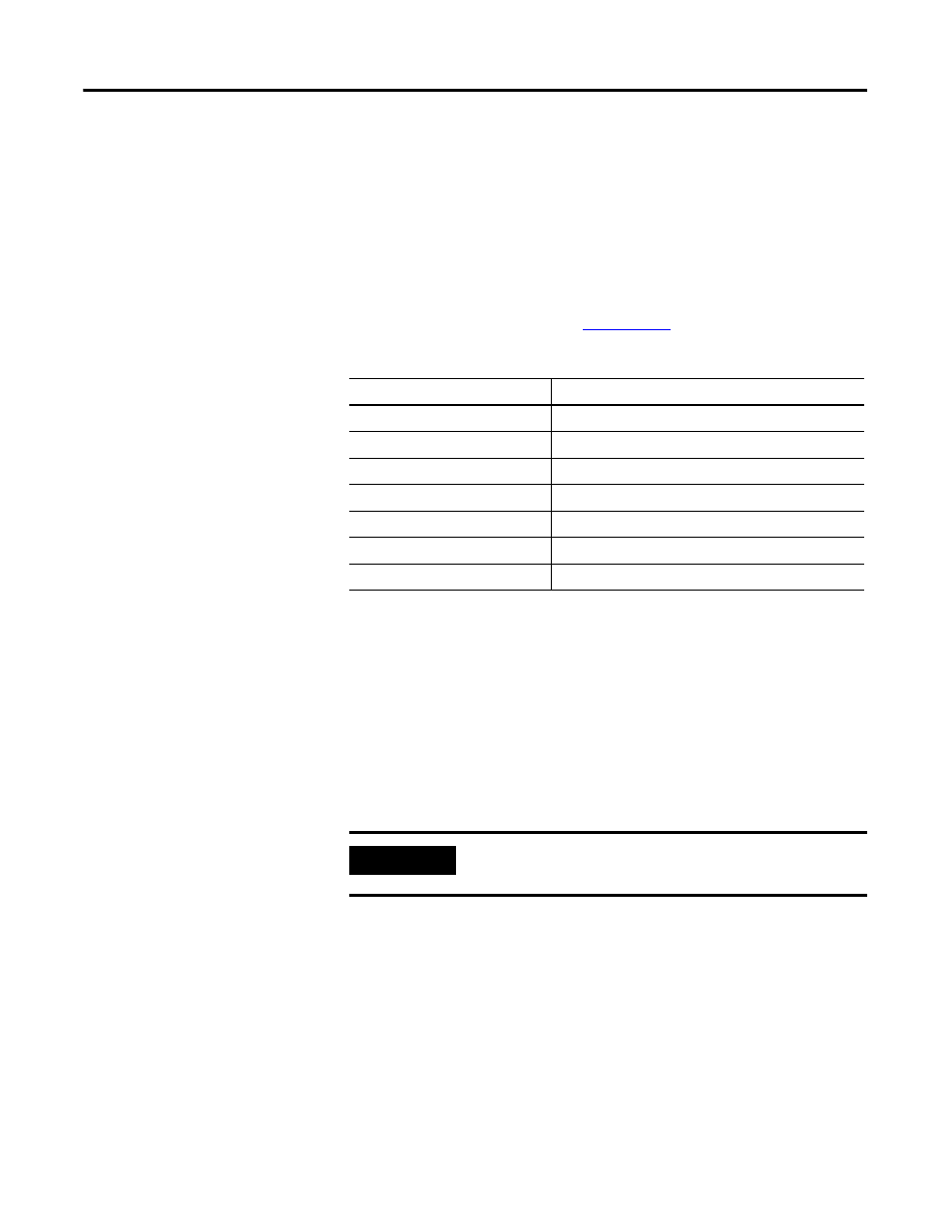
The following table shows the serial and protocol communication parameters
supported by the RS485 serial port. These parameters are set from the DS
Setting software utility for the 1758-RTU controller or the DS FloConfig
software utility for the 1758-FLO controller.. For details, refer to the DataSite
Software User Manual, publication
The RS485 port of the DataSite controller receives and sends voltage,
measured in microvolts, to other pieces of RS485 equipment. A piece of
RS485 equipment can connect with up to 32 pieces of equipment. The
recommended maximum transmission distance is 1200 m and the two ends
should have terminal resistance.
Signal grounds of the RS485 equipment are not connected together but set
according to the electrical grounding of each piece of equipment. There should
be a difference of a few volts between the grounding voltage of each piece of
RS485 equipment. The RS485 port runs in the two-wire mode.
Serial and protocol communication parameters
Parameter
Engineering value
Baud rate (bps)
2400, 4800, 9600, 19200, 38400, 57600
Communication duplex mode
Half Duplex
Parity
Odd, None or Even
Data bits
7 or 8 bits
Stop bits
1 or 2 bits
Communication protocol
Modbus RTU, Modbus ASCII, DNP3
Protocol mode
Master, Slave (DNP3 supports only Slave mode.)
IMPORTANT
When you use the shielded cable, single-end grounding by the
shielding layer is adopted.