Rs232 db-9p connector – Rockwell Automation 1758-RTU202 DataSite Hardware User Manual User Manual
Page 36
Publication 1758-UM001D-EN-P - June 2011
36 Wiring the Controller
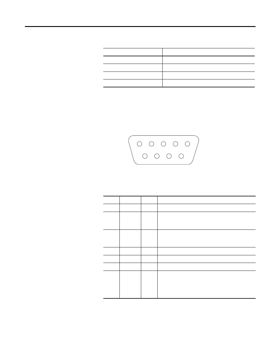
RS232 DB-9P Connector
When using RS232 serial connection, connect the interface COM of PC and
interface COM1 or COM2 of controller with data cables of 9-pin standard
connector (DB-9P).
In the following table an EFFECTIVE level means a voltage of +3V or
greater; a LEISURE level means a voltage of –3V or less.
Stop bits
1 or 2 bits
Communication protocol
Modbus RTU, Modbus ASCII, DNP3
Protocol mode
Master, Slave (DNP3 supports only slave mode.)
Connecting type
DB-9P
Pin Assignments for RS232 Connector
Pin
Function Type
Description
Pin 1
DCD
NC
This pin is not connected.
Pin 2
RXD
Input
LEISURE for being in waiting state.
EFFECTIVE for receiving data, and the RXD LED will be
blinking.
Pin 3
TXD
Output
LEISURE for being in waiting state.
EFFECTIVE for transmitted data, and the TXD LED will be
blinking.
Pin 4
DTR
NC
This pin is not connected.
Pin 5
GROUND
GND
This pin is connected to the system ground.
Pin 6
—
NC
This pin is not connected.
Pin 7
RTS
Output
EFFECTIVE if full duplex operation is selected for the port.
EFFECTIVE just before and during transmission of data if
half duplex operation is selected.
LEISURE when no data is being transmitted.
RTS LED is lighting for an EFFECTIVE level.
Serial and protocol communication parameters (Continued)
Parameter
Engineering value
5
GND
CTS
RTS
TxD
RxD
4
3
2
9
8
7
6
1
44377