Rockwell Automation 1746-BAS-T SLC 500 Basic Basic-T Modules User Manual
Page 68
Publication 1746-UM004B-EN-P - December 2005
4-20 Programming Overview
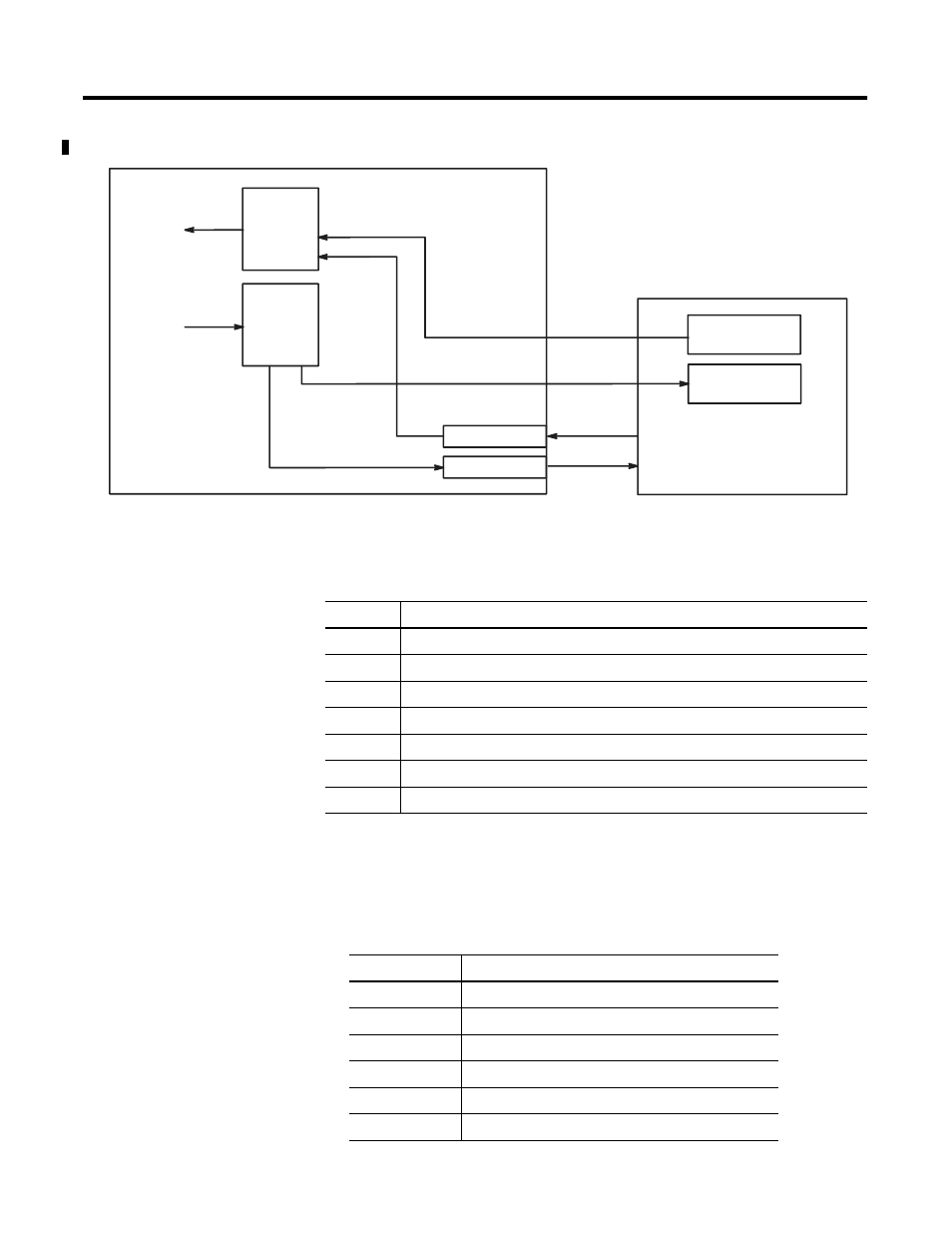
Figure 4.6 Data Flow Between the Module and SLC Processor
In addition, the commands in the following table provide status of and
control over the data transfer between the SLC processor and module.
For more information regarding the use of these commands, refer to
the BASIC Language Reference Manual, publication 1747-RM001.
The following table lists module buffer addresses. Refer to page 4-1
for more information regarding module buffer addresses.
SLC Processor
CALL 53
16 bytes
SLC OUTPUT
IMAGE
BASIC INPUT
BUFFER
BASIC
OUTPUT
BUFFER
CALL 14/15
CALL 24/25
CALL 56
CALL 54
CALL 57
16 bytes
128 bytes
128 bytes
SLC INPUT IMAGE
SLC M0
SLC M1
1746-BAS or 1746-BAS-T Module
Command Purpose
CALL 51
Checks if the CPU output image buffer was updated.
CALL 55
Checks if the CPU input image buffer was read by the processor.
CALL 58
Checks if the CPU M0 file was updated.
CALL 59
Checks if the CPU M1 file was read by the processor.
CALL 86
Checks if the DH485 interface file was updated.
CALL 87
Checks if the DH485 interface file was read by an external device.
CALL 120
Clears the module input and output buffers.
Address
BASIC Input/Output Buffer Address
M1:e.s
100...163
M0:e.s
100...163
I:e.s
200...207
O:e.s
200...207
CIF in
0...39
CIF out
0...39