Rockwell Automation 1746-NI8 SLC 500 Analog Input Modules User Manual User Manual
Page 67
8–2
Application Examples
Publication 1746Ć6.8 - April 1997
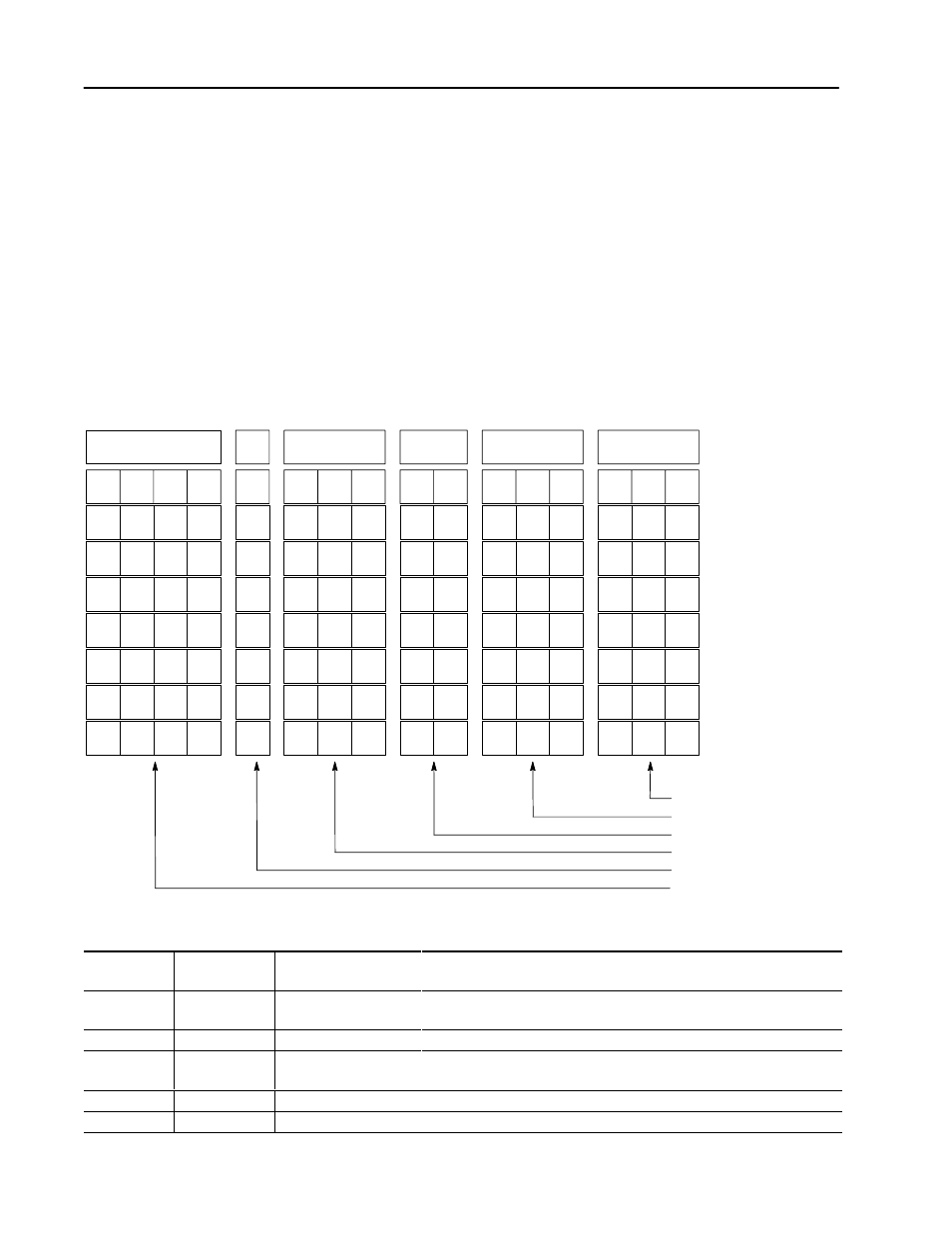
Channel Configuration
Configure channel 0 of the 1746-NI8 module with the following
setup:
•
4–20 mA input type
•
engineering units data format
•
zero data word in the event of an open circuit
•
10 Hz input filter to reject high frequency noise and provide
rejection of 60 Hz line noise
Channel Configuration Worksheet
(With Settings Established for Channel 0)
•
Input Type
•
Data Format
•
Open Circuit
•
Filter Frequency
•
Channel Enable
•
Not Used
Channel 0 - N10:0
Channel 1
Channel 2
Channel 3
ЙЙЙЙЙЙЙ
ЙЙЙЙЙЙЙ
ЙЙЙЙЙЙЙ
11
12
13
14
15
0
0
0
0
9
10
8
6
7
4
5
0
1
2
3
0
0
0
0
0
0
0
0
0
0
0
0
Bit Number
Channel 4
Channel 5
Channel 6
Channel 7
0
0
0
0
0
0
0
0
0
0
0
0
0
0
0
0
1
1
0
1
0
0
0
1
0
0
0
0
Bit Definitions:
Bits 0-2
Input Type
000 =
±
10V dc
001 = 1-5V dc
010 = 0-5V dc
011 = 0-10V dc
100 = 0-20 mA
101 = 4-20 mA
110 =
±
20 mA
111 = 0-1 mA
Bits 3- 5
Data Format
000 = engineering units
001 = scaledĆforĆPID
010 = proportional counts
011 = 1746ĆNI4 data format
100 = user defined scaling
101 = user defined scaling
110 = illegal
111 = illegal
Bits 6 and 7
Open Circuit
00 = zero
01 = upscale
10 = downscale
11 = illegal
Bits 8-10
Filter Frequency 000 = no filter
001 = 75 Hz
010 = 50 Hz
011 = 20 Hz
100 = 10 Hz
101 = 5 Hz
110 = 2 Hz
111 = 1 Hz
Bit 11
Channel Enable
0 = channel disabled
1 = channel enabled
Bits 12-15
Not Used
0000 = always make this setting