Rockwell Automation 1746-NI8 SLC 500 Analog Input Modules User Manual User Manual
Page 20
2–6
Quick Start
Publication 1746Ć6.8 - April 1997
9.
Write the ladder program.
Reference
Write the remainder of the ladder logic program that specifies how your analog input data will be
processed for your application. In this procedure the module is located in slot 1.
11
12
13
14
15
9
10
8
6
7
4
5
0
1
2
3
Channel 0 Data Word
(variable input data)
0 0 0 0
Bit Number
0 0 0 0
0 0 0 0 0 0
0 0
1746ĆNI8 Module Input Image - Data Word
Class 1
Class 3
I:1.0
channel 0 data word
16 bit integer
•
•
I:1.1
channel 1 data word
16 bit integer
•
•
I:1.2
channel 2 data word
16 bit integer
•
•
I:1.3
channel 3 data word
16 bit integer
•
•
I:1.4
channel 4 data word
16 bit integer
•
•
I:1.5
channel 5 data word
16 bit integer
•
•
I:1.6
channel 6 data word
16 bit integer
•
•
I:1.7
channel 7 data word
16 bit integer
•
•
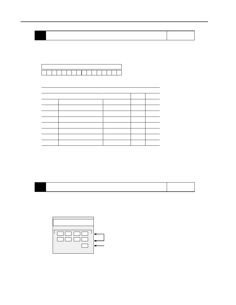
10.
Go through the system startĆup procedure.
Reference
Apply power. Download your program to the SLC processor and put the controller into Run mode.
During a normal start up, the module status LED and any enabled channel status LED turn on.
Chapter 7
(Module
Diagnostics and
Troubleshooting)
INPUT
Channel Status LEDs
Module Status LED
MODULE STATUS
CHANNEL STATUS
ANALOG
0
1
2
3
4
5
6
7
Chapter 5
(Channel
Configuration,
Data, and Status)
Chapter 6
(Ladder Logic
Configuration
Examples)
Chapter 8
(Application
Examples)
Your programming
device's user
manual.