Channel filter frequency, Channel filter frequency selection – Rockwell Automation 1746-NI8 SLC 500 Analog Input Modules User Manual User Manual
Page 38
4–77
Preliminary Operating Considerations
Publication 1746Ć6.8 - April 1997
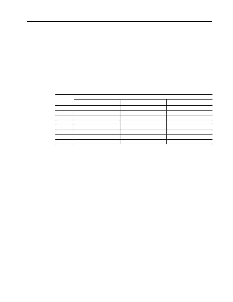
The module uses a digital low pass filter that provides noise rejection
for the input signals. The digital filter is programmable, allowing
you to select from eight filter frequencies for each channel.
Selecting a low value (i.e., 1 Hz) for the channel filter frequency
provides the best noise rejection for a channel. Selecting a high
value for the channel filter frequency provides lower noise rejection
and faster step response time. See page
4–10 for more information
on noise rejection.
The following table shows the available filter frequencies and step
response for each filter frequency.
Filter
Step Response Time
Filter
Frequency 1% Accuracy
➀
0.1% Accuracy
➀
0.05% Accuracy
➀
1 Hz
730 msec + module update time
1100 msec + module update time 1200 msec + module update time
2 Hz
365 msec + module update time
550 msec + module update time
600 msec + module update time
5 Hz
146 msec + module update time
220 msec + module update time
240 msec + module update time
10 Hz
73 msec + module update time
110 msec + module update time
120 msec + module update time
20 Hz
36.5 msec + module update time
55 msec + module update time
60 msec + module update time
50 Hz
14.5 msec + module update time
22 msec + module update time
24 msec + module update time
75 Hz
10 msec + module update time
15 msec + module update time
18 msec + module update time
no filter
0.5 msec + module update time
0.75 msec + module update time
0.75 msec + module update time
➀
The module accuracy for current inputs is 0.05%, and for voltage inputs is 0.1%.
Channel Step Response
The channel filter frequency determines the channel’s step response.
The step response is time required for the channel data word to reach
a specified percentage of its expected final value. This means that if
an input signal changes faster than the channel step response, a
portion of that signal will be attenuated by the channel filter. The
table above shows the step response for each filter frequency.
Channel Frequency
Channel CutĆOff Frequency
The channel filter frequency selection determines a channel’s cut-off
frequency, also called the –3 dB frequency. The cut-off frequency is
defined as the point on the input channel frequency response curve
where frequency components of the input signal are passed with
3 dB of attenuation. All frequency components at or below the
cut-off frequency are passed by the digital filter with less than 3 dB
of attenuation. All frequency components above the cut-off
frequency are increasingly attenuated.
Channel Filter Frequency
Selection