Rockwell Automation 1746-NI8 SLC 500 Analog Input Modules User Manual User Manual
Page 17
2–3
Quick Start
Publication 1746Ć6.8 - April 1997
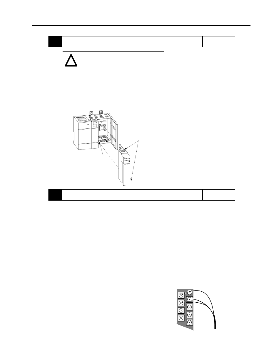
4.
Insert the 1746ĆNI8 module into the chassis.
Reference
ATTENTION: Never install, remove, or wire
modules with power applied to the chassis or
devices wired to the module.
!
Make sure system power is off; then insert the module into your 1746 chassis.
In this example procedure, local slot 1 is selected.
Important: For applications using the upper limit of the operating temperature range, the 1746ĆNI8
module (or multiple 1746ĆNI8 modules) should be placed in the right most slot(s) of the chassis. The
specification for operating temperature is:
0
°
C to 55
°
C (32
°
F to 131
°
F) in any slot except slot 0
0
°
C to 60
°
C (32
°
F to 140
°
F) in right most slot of chassis
Chapter 3
(Installation and
Wiring)
Card
Guide
Top and Bottom
Module Release(s)
5.
Connect sensor cable.
Reference
Connect sensor cable to the module's terminal block.
Chapter 3
(Installation and
Wiring)
Sensor Cable
Terminal Block
Important: Follow these guidelines when wiring the module.
•
Use shielded communication cable (Belden 8761) and keep length as short as possible.
•
Connect only one end of the cable shield to earth ground.
•
Connect the shield drain wires for channels 0-3 to the top shield terminal.
•
Connect the shield drain wires for channels 4-7 to the bottom shield terminal.
•
Shield terminals are internally connected to chassis ground which is connected to earth ground via the SLC backplane.
•
SingleĆended source commons may be jumpered together at the terminal block.
•
Channels are not isolated from each other. All analog commons are connected together internally.
•
If a differential signal source has an analog common, it can not and must not be connected to the module.
•
Common mode voltage range is $10.5 volts. The voltage between any two terminals must be less than 21 volts.
•
The module does not provide power for the analog inputs.
•
Use a power supply that matches the transmitter (sensor) specifications.
SHIELD
CH 0 (-)
CH 0 (+)
CH 1 (-)
CH 1 (+)
CH 2 (-)
CH 2 (+)
CH 3 (+)