Hardware features, 1–2 overview, Dip switches – Rockwell Automation 1746-NI8 SLC 500 Analog Input Modules User Manual User Manual
Page 12
1–2
Overview
Publication 1746Ć6.8 - April 1997
Important: Status words are only available when the module is
configured for Class 3.
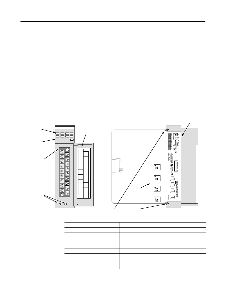
Hardware Features
The module fits into any slot, except the processor slot (0), in either
an SLC 500 modular system or an SLC 500 fixed system expansion
chassis (1746-A2).
The module contains a removable terminal block providing
connection for eight analog input channels, which is specifically
designed to interface with analog current and voltage input signals.
The channels can be wired as either single-ended or differential
inputs. There are no output channels on the module. Module
configuration is done via the user program. There are DIP switches
on the circuit board for selecting voltage or current input.
Voltage
Current
O
Cable Tie Slots
SelfĆLocking Tabs
Side Label
Removable
Terminal Block
SHIELD
SHIELD
CHL3-
CHL3+
CHL2-
CHL2+
CHL1-
CHL1+
CHL0-
CHL0+
Door Label
Channel Status
LEDs (Green)
Module Status
LED (Green)
CHL7-
CHL6-
CHL5-
CHL4-
CHL7+
CHL6+
CHL5+
CHL4+
INPUT
CHANNEL STATUS
ANALOG
0
1
2
3
4
5
6
7
MODULE STATUS
2
1
N
DIP
Switches
Voltage
Current
O
2
1
N
Voltage
Current
O
2
1
N
Voltage
Current
O
2
1
N
Hardware Feature
Function
Channel Status LED Indicators
Displays channel operating and fault status.
Module Status LED
Displays module operating and fault status.
Side Label (Nameplate)
Provides module information.
Removable Terminal Block
Provides physical connection to input devices.
Door Label
Permits easy terminal identification.
Cable Tie Slots
Secures and route wiring from module.
SelfĆLocking Tabs
Secures module in chassis slot.
Voltage/current Selection DIP Switches
Selects voltage or current input type to match the analog sensor.