Rockwell Automation 1746-NI8 SLC 500 Analog Input Modules User Manual User Manual
Page 19
2–5
Quick Start
Publication 1746Ć6.8 - April 1997
1746ĆNI8 Module Output Image - Channel Configuration
Class 1
Class 3
O:1.0
channel 0 configuration word
bit mapped field
•
•
O:1.1
channel 1 configuration word
bit mapped field
•
•
O:1.2
channel 2 configuration word
bit mapped field
•
•
O:1.3
channel 3 configuration word
bit mapped field
•
•
O:1.4
channel 4 configuration word
bit mapped field
•
•
O:1.5
channel 5 configuration word
bit mapped field
•
•
O:1.6
channel 6 configuration word
bit mapped field
•
•
O:1.7
channel 7 configuration word
bit mapped field
•
•
O:1.8
lower scale limit range 0
16 bit integer
•
O:1.9
upper scale limit range 0
16 bit integer
•
O:1.10
lower scale limit range 1
16 bit integer
•
O:1.11
upper scale limit range 1
16 bit integer
•
8.
Program the configuration.
Reference
Do the programming necessary to establish the new configuration word setting in the previous step.
1. Create integer file N10. Integer file N10 should contain one element for each channel used.
(For this example we only need one, N10:0.)
2. Enter the configuration parameters from step 7 for channel 0 into integer N10:0.
3. Program an instruction in your ladder logic to copy the contents of N10:0 to output word O:1.0.
Chapter 6
(Ladder Logic
Configuration
Examples)
Chapter 8
(Application
Examples)
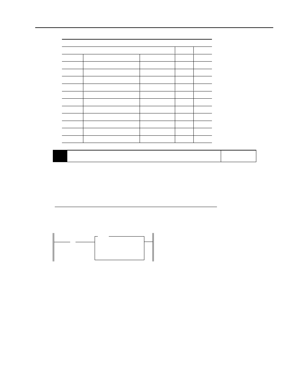
On power up, the first pass bit
(S:1/15) is set for one scan, enabling
the COPY instruction that transfers
the channel configuration word 0.
This configures and enables the
channel.
DATA FILE N10
Offset
15
14
13
12
11
10
9
8
7
6
5
4
3
2
1
0
N10:0
0
0
0
0
1
0
1
1
0
0
0
0
0
0
0
0
] [
COP
COPY FILE
Source
#N10:0
Dest
#O:1.0
Length
1
First Pass Bit
S:1
15
Initialize 1746ĆNI8