Rockwell Automation 1746-NI8 SLC 500 Analog Input Modules User Manual User Manual
Page 31
3–10
Installation and Wiring
Publication 1746Ć6.8 - April 1997
Wiring Input Devices to the 1746ĆNI8
After the analog input module is properly installed in the chassis,
follow the wiring procedure below using Belden 8761 cable.
!
ATTENTION: Care should be taken to avoid
connecting a voltage source to a channel configured for
current input. Improper module operation or damage
to the voltage source can occur.
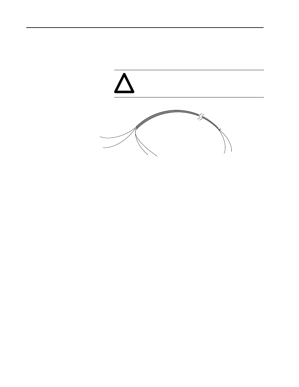
Foil Shield
Drain Wire
(Twist the drain wire and foil shield together
and connect to earth ground or to the shield
terminal on the 1746ĆNI8 module.)
Signal Wire
Signal Wire
Signal Wire
Signal Wire
(Cut foil shield
and drain wire.)
Cable
To wire your 1746-NI8 module follow these steps.
1. At each end of the cable, strip some casing to expose the
individual wires.
2. Trim the signal wires to 2-inch lengths. Strip about 3/16 inch
(5 mm) of insulation away to expose the end of the wire.
3. At one end of the cable, twist the drain wire and foil shield
together. This end of the cable will be connected to one of the
shield terminals on 1746-NI8 module. Connect shields for
channels 0–3 to the upper shield terminal, and shields for
channels 4–7 to the lower shield terminal.
4. At the other end of the cable, cut the drain wire and foil shield
back to the cable.
5. Connect the signal wires and the shield drain wire to the
1746-NI8 terminal block. Connect the other end of the cable to
the input device.
6. Repeat steps 1 through 6 for each channel on the module.