Led indicators – Rockwell Automation 1746-NI8 SLC 500 Analog Input Modules User Manual User Manual
Page 61
7–2
Module Diagnostics and Troubleshooting
Publication 1746Ć6.8 - April 1997
A failure of any channel diagnostic test causes the faulted channel
status LED to blink. All channel faults are indicated in bits 12–15 of
the channel’s status word. Channel faults are self-clearing. When
the fault conditions are corrected, the channel status LED will stop
blinking and resume steady illumination.
Important: If you clear (0) a channel enable bit (11) all channel
status information is reset.
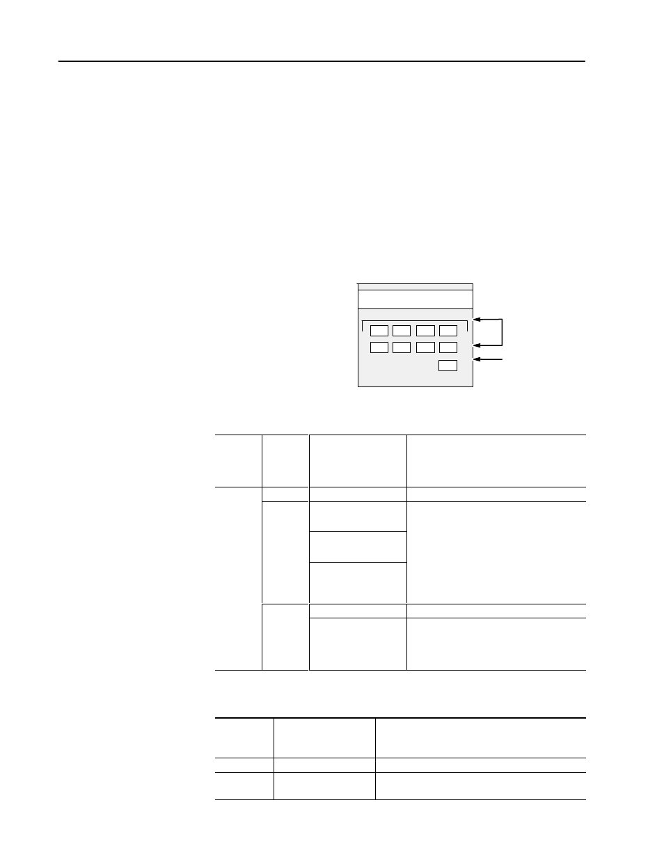
The module has nine LEDs. Eight of these are channel status LEDs
numbered to correspond to each of the input channels, and one is a
module status LED.
INPUT
Channel Status LEDs
Module Status LED
MODULE STATUS
CHANNEL STATUS
ANALOG
0
1
2
3
4
5
6
7
LED State Table
If Module
Status
LED is:
And
Channel
Status
LED is:
Indicated Condition:
Corrective action:
On
Channel Enabled
No action required.
OpenĆCircuit Condition
To determine the exact error, check the error
bits in the input image. Check the channel
fi
ti
d f
lid d t M k
Blinking
OutĆofĆRange Condition
configuration word for valid data. Make sure
that the data format is indicated correctly in bits
3-5, and that the openĆcircuit selection state
On
g
Channel Configuration
Error
3-5, and that the openĆcircuit selection state
(bits 6 and 7) is valid. Refer to the
troubleshooting flowchart on page
7-5
and to
chapter 5 for more information.
PowerĆUp
No action required.
Off
Channel Not Enabled
No action required. For an example of how to
enable a channel refer to chapter 2, Quick
Start, or chapter 6, Ladder Logic Configuration
Examples.
Module Status LED State Table
If Module
Status
LED is:
Indicated condition:
Corrective action:
On
Proper Operation
No action required.
Off
Module Fault
Cycle power. If condition persists, call your local
distributor or AllenĆBradley for assistance.
LED Indicators