Image table mapping – Rockwell Automation 1734-ADNX POINT I/O DeviceNet Adpater User Manual User Manual
Page 40
Publication 1734-UM002C-EN-P - July 2003
2-20 What is the 1734-ADN(X) Adapter?
Image Table Mapping
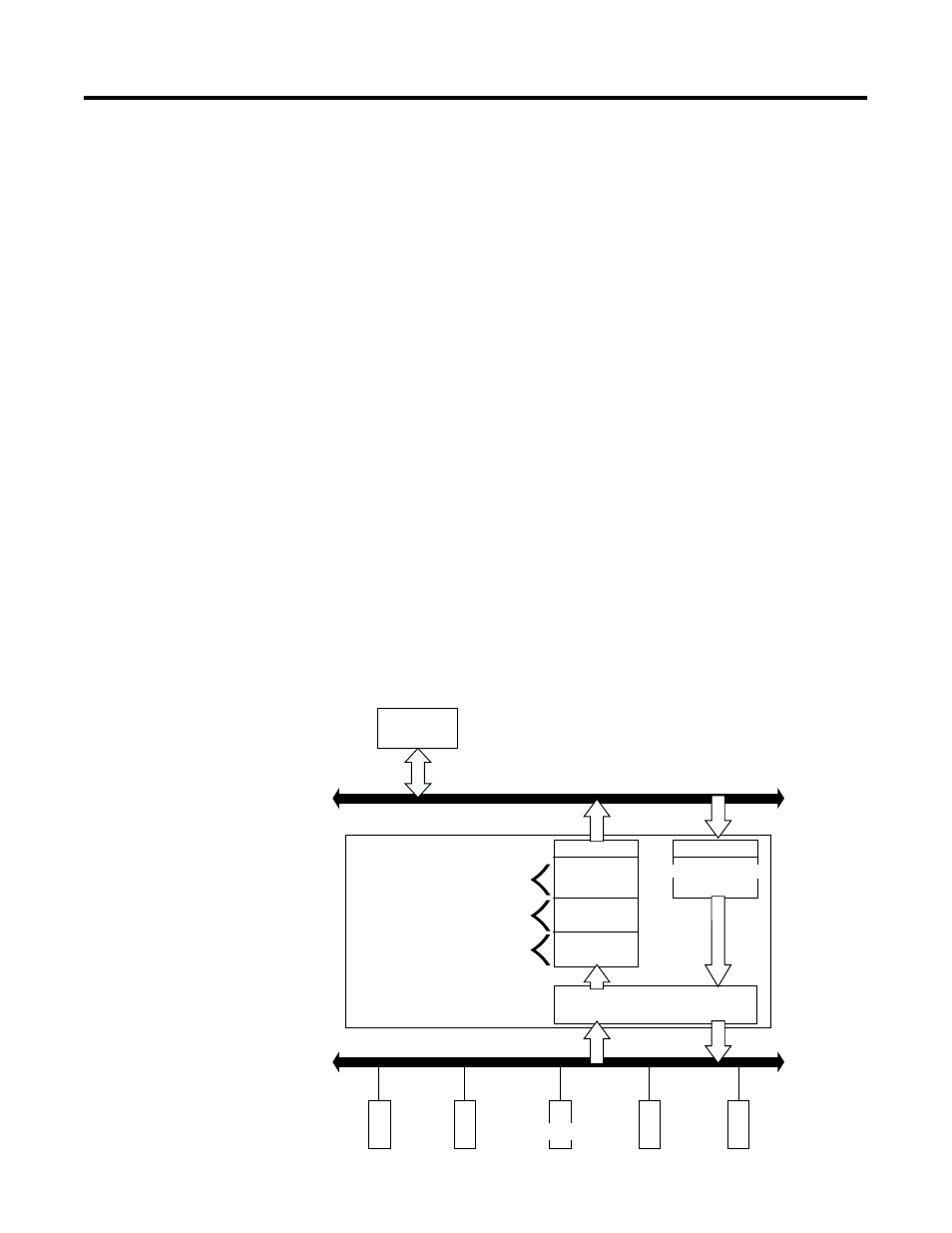
Your adapter receives data from:
• master devices (e.g., scanners) - output data is then passed to
POINT I/O modules
• input modules - input data is passed to the scanner
The adapter must map the data it receives to its internal memory
before passing it to the appropriate device. The I/O map for a module
is divided into:
• read bytes - input and status bytes
• write bytes - output and configuration bytes
The data is mapped by 3 buffers for input data (each representing an
I/O connection on the primary DeviceNet) and 1 buffer for output
data (representing data sent for Poll or COS connections on the
primary DeviceNet).
The number of read bytes or write bytes can be 2 or more. The length
of each I/O module’s read bytes and write bytes vary in size
depending on module complexity. Each I/O module supports at least
1 input byte or 1 output byte. Status and configuration are optional,
depending on the module.
The graphic below shows how the adapter maps information.
DeviceNet
Scanner
INPUT DATA
DeviceNet
Subnet
DeviceNet
DeviceNet Poll Buffer
42406
248 bytes
+ 2 bytes status
1734-ADN
DeviceNet Strobe Buffer
DeviceNet COS/CYC Buffer
OUTPUT DATA
Poll OR COS (inst 2)
248 + 2 bytes
6 + 2 bytes
248 bytes
+ 2 bytes status
I/O MAPPING
(each node up to 4 mappings each direction)
Subnet MODULES