Rockwell Automation 1771-OFE/B Analog Output Module User Manual User Manual
Page 6
Preface
P–2
Publication 1771Ć6.5.30 - November 1998
Appendices
Title
A
Specifications
B
Block Transfer with MiniĆPLCĆ2 and PLCĆ2/20 Processors
C
Data Table Formats
You can install your output module in any system that uses
Allen-Bradley programmable controllers that have block transfer
capabilities and the 1771 I/O structure.
For more information on your programmable controllers, contact
your nearest Allen-Bradley office.
The 1771-OFE module can be used with any 1771 I/O chassis.
Communication between the discrete analog module and the
processor is bidirectional; the processor block-transfers output data
through the output image table to the module and block-transfers
input data from the module through the input image table. The
module also requires an area in the data table to store the read block
transfer data and write block transfer data. I/O image table use is an
important factor in module placement and addressing selection.
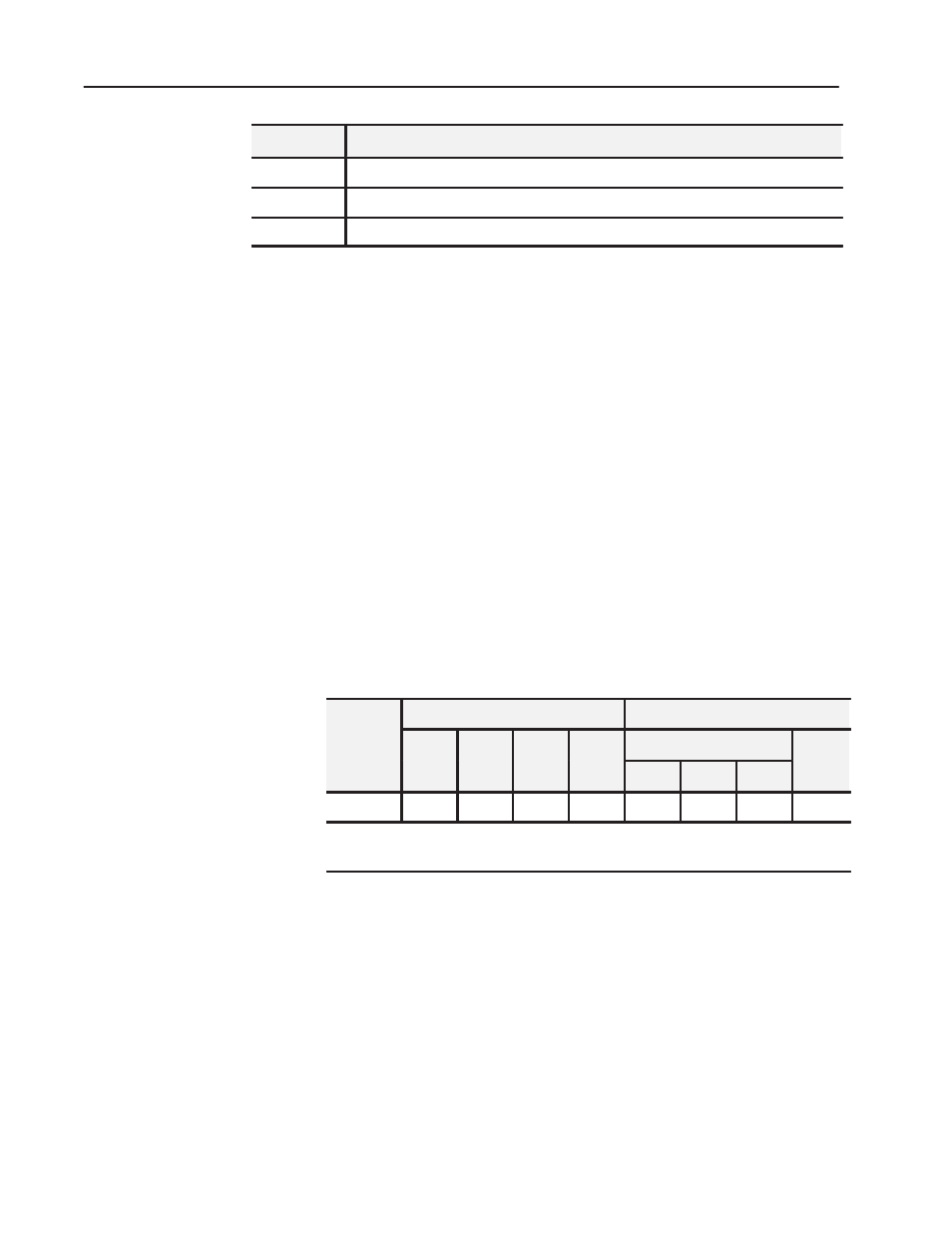
Compatibility and data table use is listed in the following table.
Table P.A
Compatibility and Use of Data Table
Use of Data Table
Compatibility
Catalog
Number
Input
Image
Output
Image
Read
Block
Write
Block
Addressing
Chassis
Image
Bits
Image
Bits
Block
Words
Block
Words 1/2ĆSlot
1ĆSlot
2ĆSlot
Series
1771ĆOFE
8
8
5
13
Y
Y
Y
A, B
A = Compatible with 1771ĆA1, ĆA2, ĆA4
B = Compatible with 1771ĆA1B, ĆA2B, ĆA3B, ĆA3B1, ĆA4B
Y = Compatible without restriction.
•
You can place your module in any I/O module slot of the I/O
chassis.
•
You can put two output modules in the same module group.
•
Do not put the module in the same module group as a discrete
high density module.
•
Avoid placing output modules close to ac modules or high voltage
dc modules.
For a list of publications with information on Allen-Bradley
programmable controller products, consult our publication index
(SD499).
Related Products
Product Compatibility
Related Publications