Rockwell Automation 1771-OFE/B Analog Output Module User Manual User Manual
Page 45
4-9
Publication 1771Ć6.5.30 - November 1998
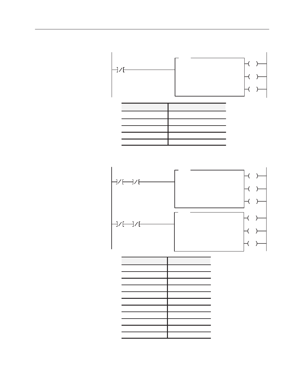
Figure 4.6
PLCĆ5 Example Program 1
N10:0
15
BTW
BLOCK XFER WRITE
Rack Address:
Group Address:
Module Address:
Control Block:
0
0
0
N10:0
Data File:
Length:
N10:5
13
EN
DN
ER
Continuous:
N
1
Rung 1
The BTW is writing in an
asĆfastĆasĆpossible" mode. As soon as
the instruction executes, it is reenabled for
another transfer. Instruction execution
could also be scheduled using a timer
done bit or some other input condition.
Program Action (Example 1)
Module Location
Rack 0, Module Group 0, Slot 0
File Configuration
Control Array
N10:0
Data File
N10:5
Configuration Word
N10:9
Enable Bit
N10:0/15
Figure 4.7
PLCĆ5 Example Program 2
N10:0
15
BTR
BLOCK XFER READ
Rack Address:
Group Address:
Module Address:
Control Block:
0
0
0
N11:0
Data File:
Length:
N11:5
5
EN
DN
ER
Continuous:
N
N11:0
15
N10:0
15
BTW
BLOCK XFER WRITE
Rack Address:
Group Address:
Module Address:
Control Block:
0
0
0
N10:0
Data File:
Length:
N10:5
13
EN
DN
ER
Continuous:
N
N11:0
15
1
2
Program Action (Example 2)
Rung 1
The enable bits of both instructions
alternate execution between rungs.
This rung is executed first. When the
BTR is done, both enable bits are off
until the next rung is scanned at which
time the BTW is enabled.
Rung 2
The BTW is writing in an
asĆfastĆasĆpossible" mode. As soon as
the instruction executes, it is reenabled for
another transfer. Instruction execution
could also be scheduled using a timer
done bit or some other input condition.
Module Location
Rack 0, Group 0, Slot 0
File Configuration
BTR
Control Array
N11:0
Data File
N11:5
Output Data Image
N11:5 through N11:8
Status Word
N11:9
Enable Bit
N11:0/15
File Configuration
BTW
Control Array
N10:0
Data File
N10:5
Configuration Word
N10:9
Enable Bit
N10:0/15