Rockwell Automation 1771-OFE/B Analog Output Module User Manual User Manual
Page 47
4-11
Publication 1771Ć6.5.30 - November 1998
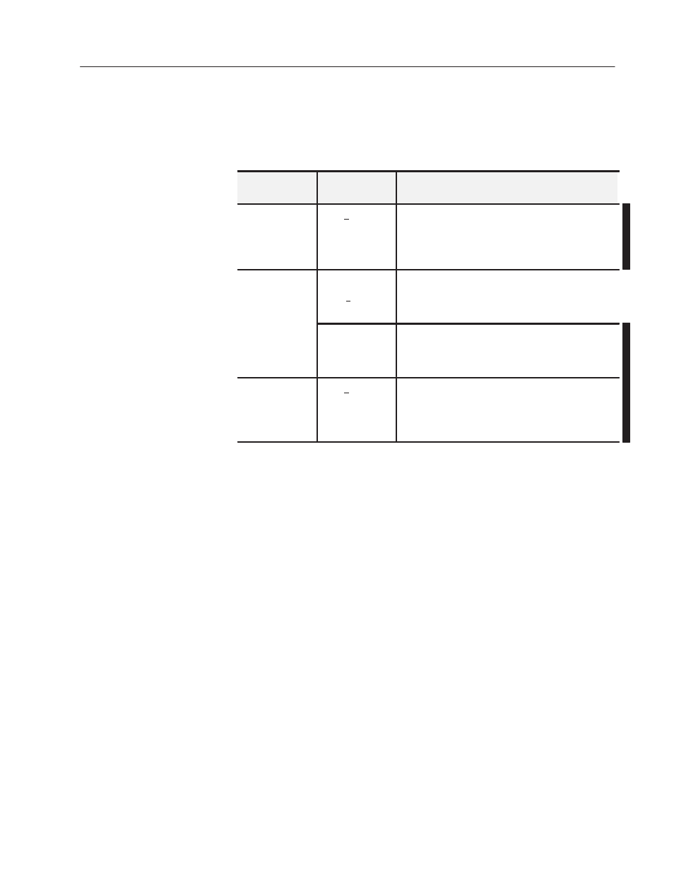
All Four Channels Scaled
To scale all four channels, enter a block length of 00 and enter the
appropriate scaling values for the four channels, as shown in the
following table.
If You Want
And Channel Is
Configured for:
Then Enter:
No Channels
Scaled
+10V,
0Ć10V,
1Ć5V,
4Ć20 mA,
0Ć50mA
A Block Length of 5
No Scaling Information
Fewer than Four
+10V
A Block Length of 00
Appropriate Scaling Values
Ć4095 Minimum Scaling Value and +4095 Maximum
Scaling Value for Unscaled Channel(s)
Channels Scaled
0Ć10V,
1Ć5V,
4Ć20 mA,
0Ć50mA
A Block Length of 00
Appropriate Scaling Values
0 Minimum Scaling Value and 4095 Maximum Scaling
Value for Unscaled Channels
All Four Channels
Scaled
+10V,
0Ć10V,
1Ć5V,
4Ć20 mA,
0Ć50mA
A Block Length of 00
Appropriate Scaling Values
Block Transfer Boundary Word Ć PLCĆ2 Family Processors Only
The purpose of the boundary word is to tell the processor not to
search for additional block transfer addresses.
You set the boundary word by entering one word (16 bits) of zeros in
the timer/counter accumulated value area of the data table, after the
word containing the last block transfer module address.
For example, if the last block transfer data address in the
accumulated value area of the data table is 035, the block transfer
boundary word is addressed as 036. Figure 4.8 shows the data table
structure and a sample GET/PUT instruction used to program a block
transfer boundary word.