Calibrating your output module, Chapter – Rockwell Automation 1771-OFE/B Analog Output Module User Manual User Manual
Page 53
Chapter
6
Publication 1771Ć6.5.30 - November 1998
Calibrating Your Output
Module
In this chapter, you will read how to calibrate your output module.
Forinformation on
See page
Tools and test equipment . . . . . . . . . . . . . . . . . . . . . . . . . . . 6-1
Calibrating your module . . . . . . . . . . . . . . . . . . . . . . . . . . . . 6-1
Voltage Output version (1771ĆOFE1) . . . . . . . . . . . . . . . . . . 6-2
Current Output version (1771ĆOFE2) . . . . . . . . . . . . . . . . . . . 6-5
Current Output version (1771ĆOFE3) . . . . . . . . . . . . . . . . . . . 6-9
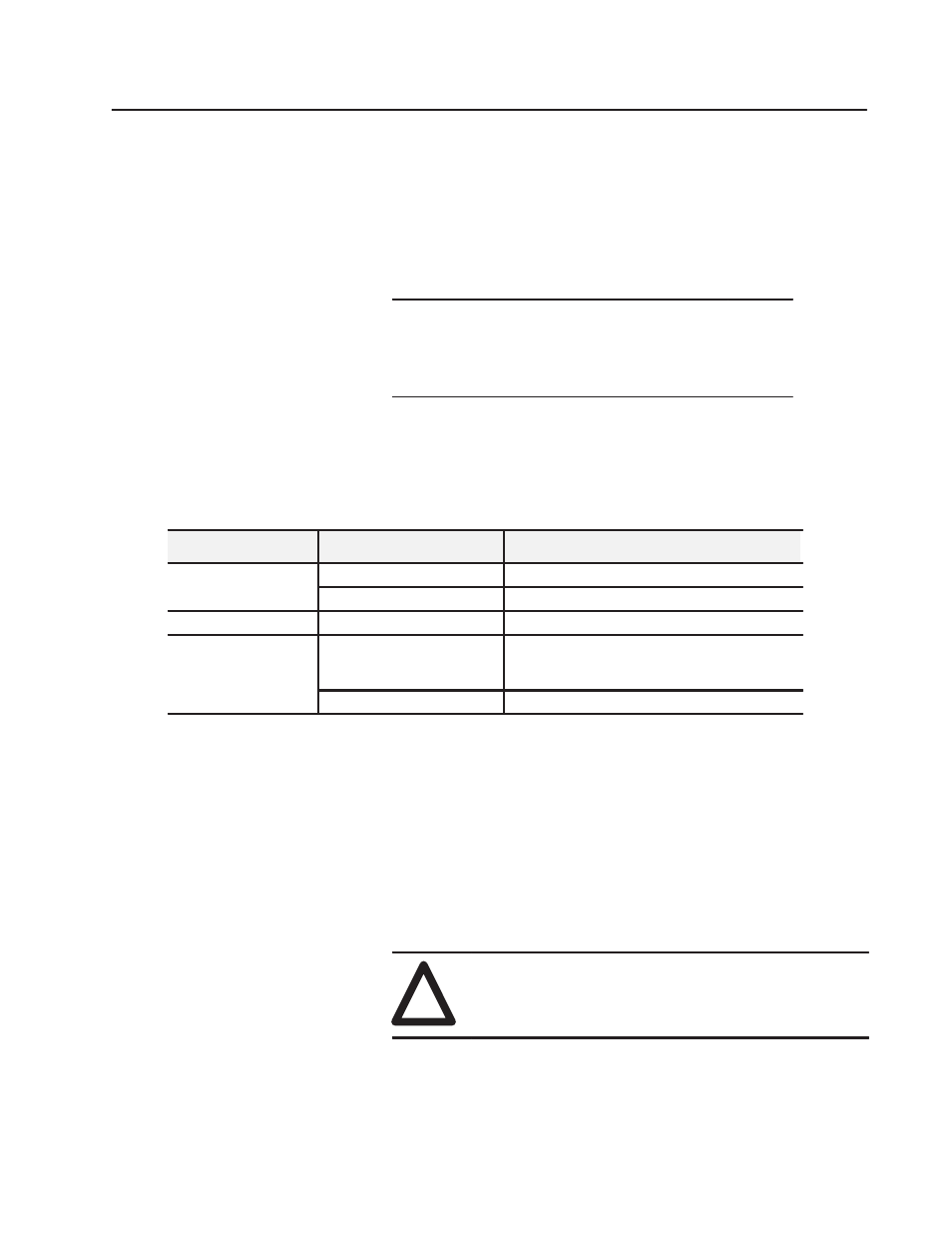
Table 6.A lists tools and test equipment required for module
calibration.
Table 6.A
Test Equipment
Used On:
Equipment
Description
Voltage Versions
5Ć1/2 Digit Voltmeter
0.01% Accuracy Minimum.
Voltage Versions
4 Load Resistors
1.0K or Greater, 0.25W, 1.0% (P/N 628217Ć01)
Current Versions
4 Load Resistors
250 ohm or Greater, 0.25W, 0.01% (P/N 940719Ć01)
Both Voltage and Current
Small Jeweler's Screwdriver
or
Pot Tweeker" Alignment Tool
Newark Electronics
500 North Pulaski Road
Chicago, IL 60624
Backplane Extender Card
Cat. No. 1771ĆEX
The analog output module is shipped from the factory already
calibrated. If it becomes necessary to recalibrate the analog output
module, you must calibrate it in an I/O chassis. The module needs to
communicate with the processor. Calibration consists of two tasks:
•
preparing the module for calibration
•
calibrating each channel
The calibration procedure for the voltage output version module is
different from the calibration procedure for the current output
version module. Refer to the appropriate section for your module.
!
ATTENTION: Do not attempt calibration without
reading and thoroughly understanding all steps in this
procedure. Also, do not attempt to calibrate this
module in an operating system.
ChapterObjectives
Tools and Test Equipment
Calibrating Your Module