Rockwell Automation 1771-OFE/B Analog Output Module User Manual User Manual
Page 13
1-3
Publication 1771Ć6.5.30 - November 1998
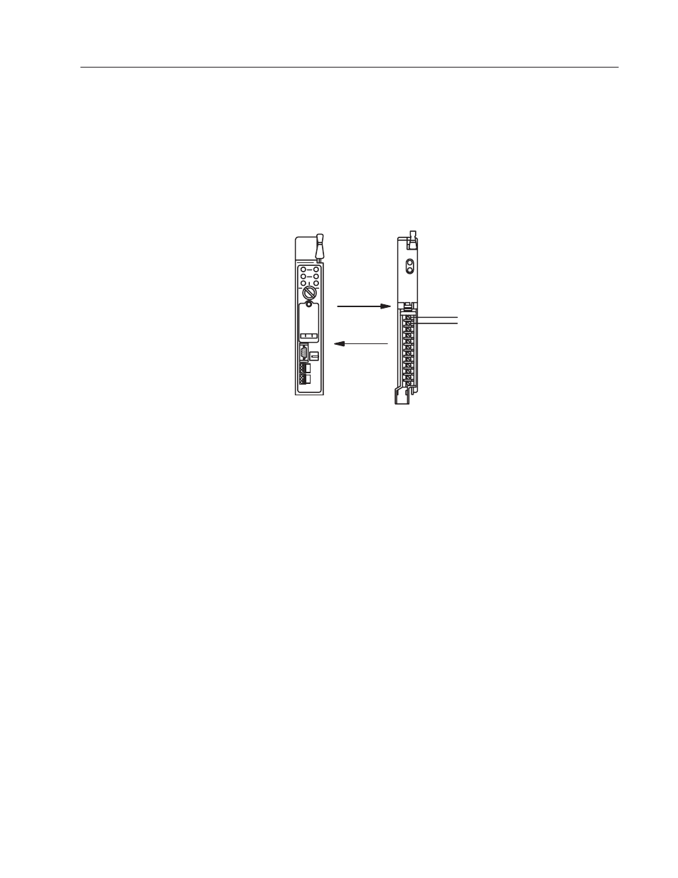
The processor transfers data to the module (block transfer write) and
from the module (block transfer read) using BTW and BTR
instructions in your ladder diagram program. These instructions let
the processor send output values to the module, establish the
module’s mode of operation (see illustration below) and receive
status information from the module.
Communication Between Processor and Module
+
–
2
1
3
To analog output devices
BTW
Programmable
Controller
Analog Output Module
Cat. No. 1771ĆOFE
12876
BTR
4
5
1. The processor transfers your configuration and output data to the
module via a block transfer write instruction.
2. The module converts the data into proportional voltage or current
outputs.
3. These module outputs drive external analog devices.
4. When instructed by your ladder program, the processor performs
a read block transfer of output values and module status.
5. The processor and module determine that the transfer was made
without error.
6. Your ladder program can use and/or move the data (if valid)
before it is written over by the transfer of new data in a
subsequent transfer.
The accuracy of your output module is described in Appendix A.
In this chapter you read about the functional aspects of the output
module and how the module communicates with the programmable
controller.
How Analog Modules
Communicate with
Programmable Controllers
Accuracy
Chapter Summary