Rockwell Automation 1771-OFE/B Analog Output Module User Manual User Manual
Page 58
6-6
Publication 1771Ć6.5.30 - November1998
Channel Calibration
1. Disconnect your analog device wires from the module’s field
wiring arm.
Important: If you have a spare or unused field wiring arm, you may
want to temporarily switch it with the module’s present
field wiring arm. You can use this spare arm for test
purposes in order to avoid disconnecting your analog
device wires.
Important: The accuracy of this calibration procedure is dependent
upon the precision of your load resistors. We suggest
using resistors with a tolerance of 0.01%. You should
be able to attain voltage readings to +2mV. (If you use
resistors of a value different from 250 ohms, you should
be able to attain voltage readings of +0.05% of V out.)
If you require greater accuracy, you need to use load
resistors with tolerances less than 0.01%.
Use load resistors with values of 250 ohms. For greater accuracy,
you can use a resistor that more closely approximates your actual
device load.
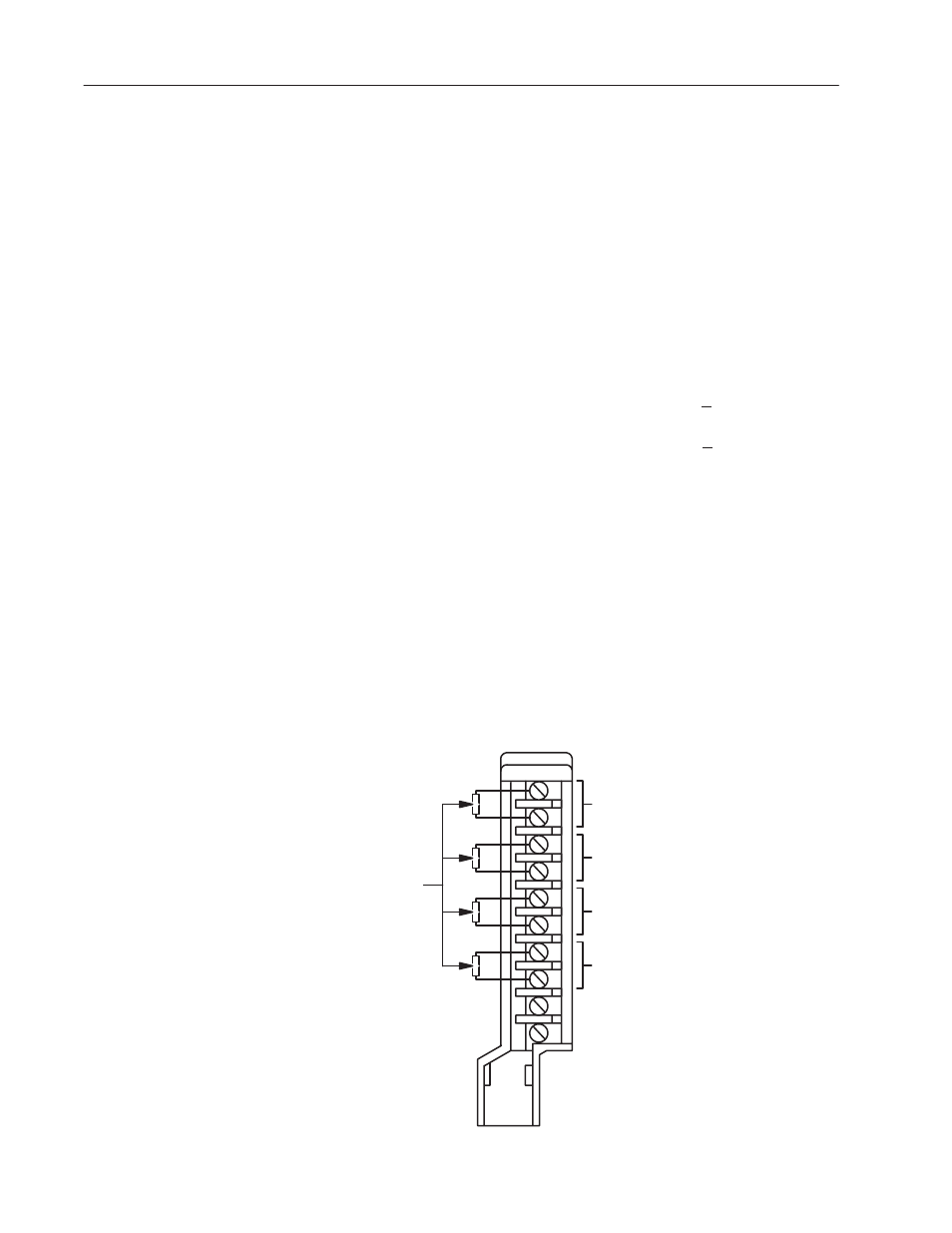
2. Attach a resistor with a value of 250 ohms across Channel 1 (the
top two screws) of the field wiring arm.
3. Attach three more 250 ohm resistors across the remaining three
channels on the field wiring arm just as you did in step 2
(Figure 6.4).
Figure 6.4
Resistor Placement on Field Wiring Arm
A
0
1
2
3
4
5
6
7
8
Channel 1
Channel 2
Channel 3
Channel 4
250 ohm
resistors
12991
Field Wiring Arm