Rockwell Automation 1771-OFE/B Analog Output Module User Manual User Manual
Page 44
4-8
Publication 1771Ć6.5.30 - November 1998
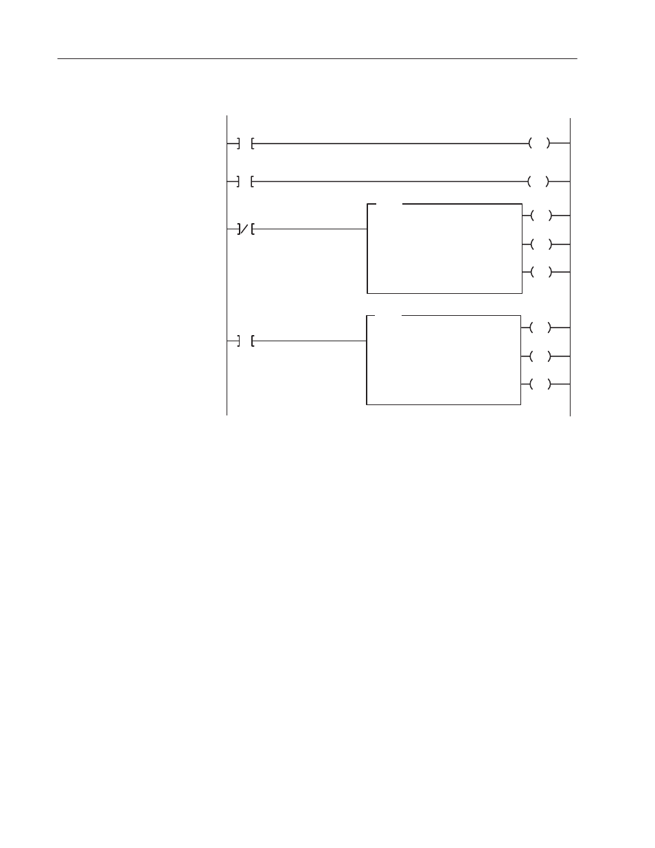
Figure 4.5
PLCĆ3 Example Program
U
15
L
05
FB001:0000
B0000
00
00
00
BTR
BLOCK XFER READ
Rack Address:
Group Address:
Module Address:
Data Address:
001
0
1 = High
FB003:0001
Length:
CNTL:
0
FB001:0000
LE
CNTL
12
DN
CNTL
15
ER
CNTL
13
B0000
00
BTW
BLOCK XFER WRITE
Rack Address:
Group Address:
Module Address:
Data Address:
001
0
1 = High
FB002:0001
Length:
CNTL:
0
FB001:0000
LE
CNTL
02
DN
CNTL
05
ER
CNTL
03
Rung Number RM0
Rung Number RM2
Rung Number RM3
Rung Number RM1
B0000
B0000
FB001:0000
Table 4.C
PLCĆ3 Data Table Word Assignments for Example 1
Start = FB002:0000
Word #
0
1
2
3
4
5
6
7
00000
0000
2048
1024
0150
0350
0100
0000
4095
00008
0000
4095
0020
0275
0100
0500
The PLC-5’s bidirectional program is very simple because the
processor handles the enable bits and ensures valid data. Two
examples are shown. The first is a write-only program you can use
when module status is not required. The second is a read/write
program.
Important: If the 1771-OFE module is configured in BCD data
format and you are using a PLC-5 processor, extra
programming will have to be added to the ladder
program (i.e. a CPT or TOD instruction) to convert
binary data to BCD data before it is transferred to the
1771-OFE module’s block transfer write data file. Also,
when checking your program’s operation, remember to
verify proper output voltage/current values based on the
data values sent to the module.
Block Transfer
Programming Ć PLCĆ5
Family Processors Only