Example slc block transfers -5, Example slc block transfers – Rockwell Automation 1336-GM1 Remote I/O Communications Module User Manual
Page 57
Using Block Transfer Messages
5–5
Example SLC Block Transfers
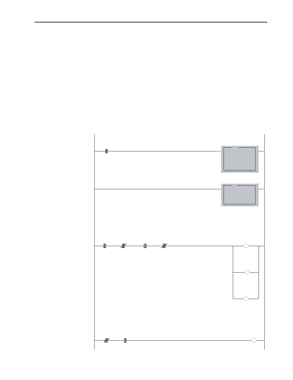
Figure 5.5 and the following data file illustrate an example block
transfer program from an SLC controller to a Remote I/O
communications module. This program uses the first block transfer
area in the scanner located in the first slot. It also uses data files N10
and B3.
The example data file contains the data needed to request a read full
of parameter 78. The length of the block transfer data file is loaded
into N10:1. The value 0 is loaded into N10:2 for the rack, group, slot
address for the block transfer because this address is 0, 0, 0 (refer to
page 5–7). Data for the BTW is loaded into N10:10. Once the data
has been loaded, the user enabled bit B3:0/0 is set. When the block
transfers have completed, the BTR data is copied into N10 starting at
N10:100 and B3:0/0 is cleared by the program.
Figure 5.5.
Example for an SLC-500
This rung clears the Virtual BT Command word on the first scan.
This ensures that the Block Transfer logic starts up reliably.
0000
S:1
15
First Pass
MOV
Move
Source
0
0<
Dest
N10:0
-32640<
MOV
This rung copies the BT Status buffer from the 1747-SN into the SLC into a
file that we will refer to as the Virtual BT Status Buffer.
0001
COP
Copy File
Source
#M1:1.100
Dest
#N10:100
Length
74
COP
If the user logic is calling for a Block Transfer message to occur and the Gx1 is ready to receive a BTW,
this rung sets up the BT buffer for a BTW and then enables it.
0002
B3:0
0
User
Logic
I:1.0
10
1747-SN
BTR
Available
I:1.0
13
1747-SN
BTW
Available
N10:0
15
Virtual
BT.EN
Bit
U
N10:0
7
Virtual
BT.Type
Bit
0 = BTW
1 = BTR
L
N10:0
15
Virtual
BT.EN
Bit
U
N10:100
13
Virtual
BT.DN
Bit
This rung turns off the Virtual BT_Enable bit when the BTW has completed.
0003
N10:0
7
Virtual
BT.Type
Bit
0 = BTW
1 = BTR
N10:100
13
Virtual
BT.DN
Bit
U
N10:0
15
Virtual
BT.EN
Bit