Rockwell Automation 1336-GM1 Remote I/O Communications Module User Manual
Page 38
3–8
Installing the Module
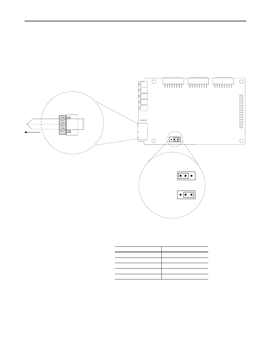
8. If the module is the last device on the Remote I/O link, either user
the internal termination resistor (J2) or an external termination
resistor. If the Remote I/O link uses 230Kbps, you must use an
external 82 ohm termination resistor.
Important: Use only one type of termination (internal or external),
Figure 3.8
Using a Termination Resistor
9. Reapply power to the SCANport product.
10. Apply power to the Remote I/O link. The module is now
installed. Its LEDs are as follows:
You are now ready to create a ladder logic program.
Important: If your LEDs are different, refer to Chapter 6.
J2
1
2
3
1
2
3
1
2
3
Not Last Device,
(Factory Default)
Last Device on link,
Termination
Resistor Inserted
Enables 150 ohm
Termination Resistor
Blue
Shield
Clear
To
Another
Remote I/O
Link Device
2
1
I50 Ohm
or
82 Ohm
1 watt
+/-10%
Sh
External Termination
Internal Termination
LED
Status
Fault
Red (Blinking)
SCANport STS
Green or amber
➀ ➁
Health
Green or amber
➁
Rem I/O ACT
Off
Rem I/O STS
Off
➀
This LED is off if the module use firmware 2.xx or lower.
➁
Early versions of the module use amber LEDs.