Rockwell Automation 1336-GM1 Remote I/O Communications Module User Manual
Page 56
5–4
Using Block Transfer Messages
Figure 5.4
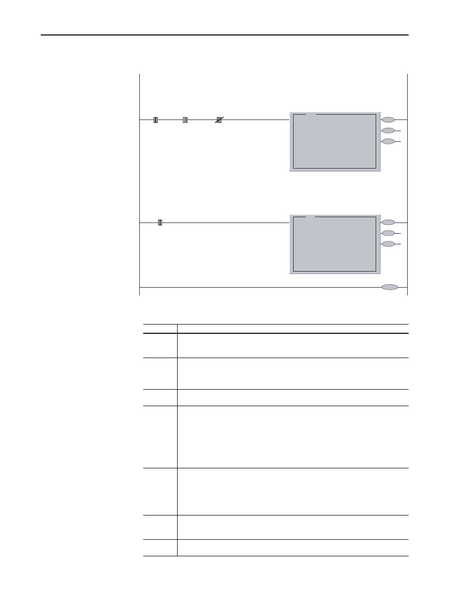
Example for a PLC-5/20, PLC-5/40, PLC-5/60, PLC-5/80
The following table defines the contents of the example PLC block
transfer messages (Figure 5.3 and Figure 5.4).
This rung performs a Block Transfer Write to the 1203-GD1 at Rack Address 1, Starting Group 0
(the Module number is always 0 with these adatpers). The data instructs the adapter to send a SCANport message.
When this message has completed, the response can be read with a BTR.
0000
B3:0
0
User
Logic
I:010
15
BTW
Available
I:010
12
BTR
Available
EN
DN
ER
BTW
Block Transfer Write
Module Type Generic Block Transfer
Rack
001
Group
0
Module
0
Control Block
BT11:0
Data File
N12:0
Length
64
Continuous
No
BTW
This rung performs a Block Transfer Read from the 1203-GD1 at Rack Address 1, Starting Group 0
(the Module number is always 0 with these adapters). The response contains the data read from the SCANport Product
(as instructed by the previous BTW).
0001
I:010
12
BTR
Available
EN
DN
ER
BTR
Block Transfer Read
Module Type Generic Block Transfer
Rack
001
Group
0
Module
0
Control Block
BT11:1
Data File
N12:70
Length
64
Continuous
No
BTR
0002
END
Content
Description
Rack
The rack address is determined by the switch settings on the Remote I/O module. (Refer to
Chapter 2.)
In Figure 5.3 and Figure 5.4, rack address 1 is used.
Group
The group number is the first group in the rack associated with the Remote I/O module. This
is called the starting group. It is determined by the size of the rack. (Refer to Chapter 2.)
In Figure 5.3, the rack has been set up as a full 8 group rack; therefore, the starting group 0 is
used.
Module
The module number is associated with the block transfer in the associated slot. This will
always be 0.
Control
Block
The control block is a predefined set of words that contain bit information associated with the
block transfer function. In the PLC-5/15 and PLC-5/25, the control block requires 5
contiguous words. In the PLC 5/40 and 5/60 the control block may be either an integer type,
and would require 5 contiguous words, or a block transfer type and would require 1 element.
In Figure 5.3, words N11:0 through N11:4 have been reserved for the bit array in the BTW
block. Words N11:5 through N11:9 have been reserved for the BTR block.
In Figure 5.4, element BT11:0 has been reserved for the bit array in the BTW block. Element
BT11:1 has been reserved for the BTR block.
Data File
The data file is the address of the message sent by the BTW or received by the BTR block. It
contains both header and data information. The number of words required for the data file is
dependent on the type of message being sent. Refer to Appendix B for information regarding
the header and data that must be included in the data file for each message.
In Figure 5.3 and Figure 5.4, N12:0 is the first word in the data file for the BTW block and
N12:70 is the first word for the BTR block.
Length
Length specifies the length of the block transfer message in words. It varies depending on the
type of message being sent. The BTW and BTR instruction lengths may be different. Refer to
the message examples in Appendix B for the minimum lengths required for each message.
Continuous Continuous specifies whether the block transfer block is to be executed continuously or only
when the rung is true. This should always be set to No.