Settings for the ladder logic program examples -5, Settings for the ladder logic program examples, Remote i/o communications module settings – Rockwell Automation 1336-GM1 Remote I/O Communications Module User Manual
Page 43
Creating Ladder Logic Programs
4–5
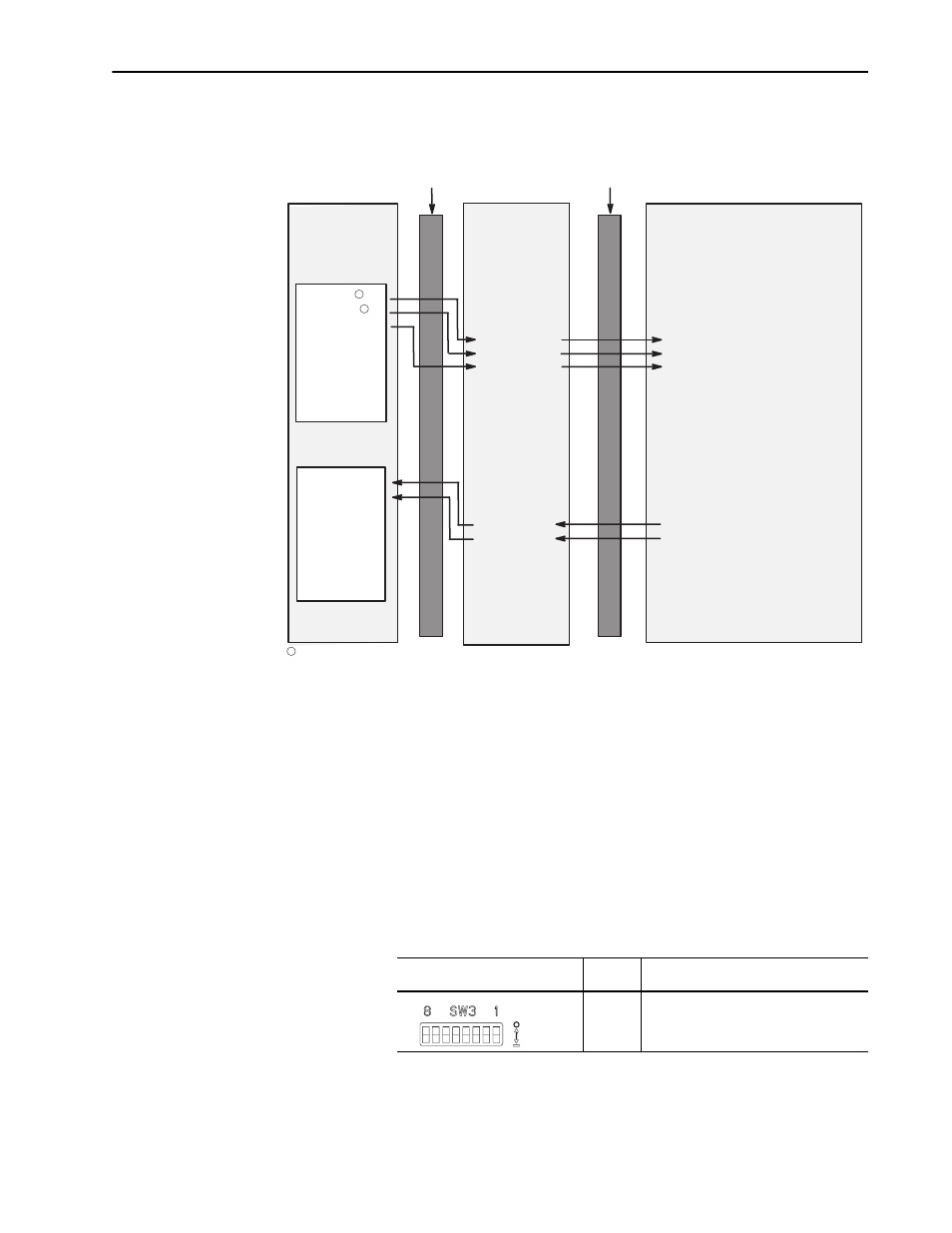
Figure 4.2 illustrates the first scan in Example Application 3.
Figure 4.2
Example Scan using Datalinks
Settings for the Ladder Logic
Program Examples
The example ladder logic programs in this manual use the following
settings.
Remote I/O Communications Module Settings
The Remote I/O module used for examples in this manual is
connected to a 1336 PLUS drive. It is configured for the following:
•
Rack Address = 2
•
Rack Size = 1/2 Rack
•
Starting Group = 0
DIP switches on SW3 are set as follows:
Remote I/O
Communications
Module
Block Transfer
Logic Command
Reference
Datalink A1
Datalink A2
Datalink B1
Datalink B2
Datalink C1
Datalink C2
Datalink D1
Datalink D2
Block Transfer
Logic Status
Feedback
Datalink A1
Datalink A2
Datalink B1
Datalink B2
Datalink C1
Datalink C2
Datalink D1
Datalink D2
1336 PLUS Drive
Controller
Image
Output Image
O:010 = 27
O:011 = 123
O:012 = 27
O:013
O:014
O:015
O:016
O:017
I:010 = 27
I:011 = 123
I:012
I:013
I:014
I:015
I:016
I:017
Input Image
Message Handler
Logic Command
Reference
P111 (Data In A1) = Sends "27" to P112
P112 (Data In A2) = Sends "123" to P27
P113 (Data In B1) = Sends "27" to P120
P114 (Data In B2)
P115 (Data In C1)
P116 (Data In C2)
P117 (Data In D1)
P118 (Data In D2)
Message Handler
Logic Status
Feedback
P119 (Data Out A1) = Gets "27" from P112
P120 (Data Out A2) = Gets "123" from P27
P121 (Data Out B1)
P122 (Data Out B2)
P123 (Data Out C1)
P124 (Data Out C2)
P125 (Data Out D1)
P126 (Data Out D2)
Remote I/O
SCANport
1
In this example scan, the parameter being changed is P27-[Preset Freq 1]. Its new value will be 123.
1
1
Switch
Settings
8 ---> 1
Description
00001110 Logic command/status, reference/
feedback, and datalink A are enabled. All
other features are disabled.
Off = 0
On = 1