Locating the dip switches -2, Locating the dip switches – Rockwell Automation 1336-GM1 Remote I/O Communications Module User Manual
Page 18
2–2
Configuring the Module
Locating the DIP Switches
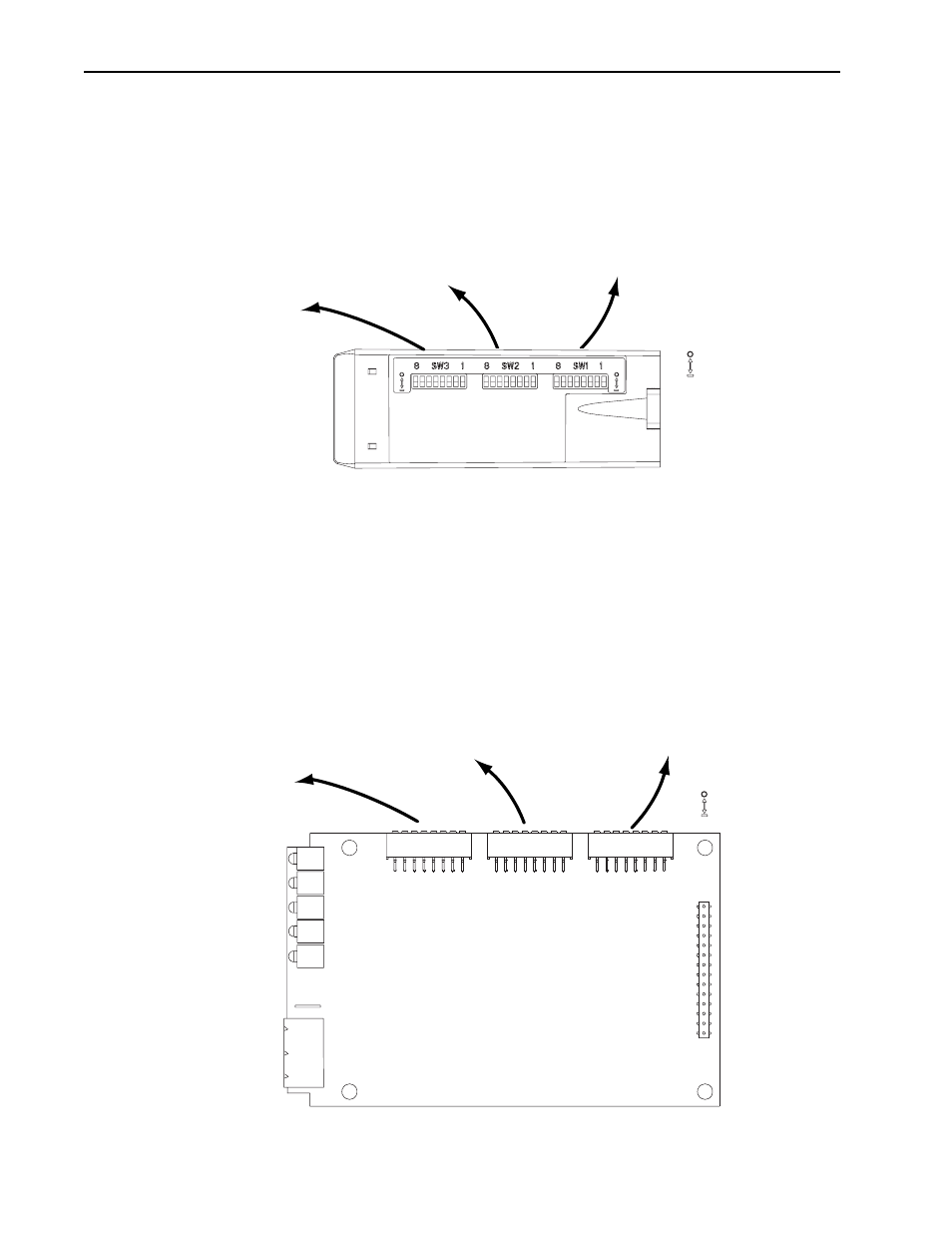
Figure 2.1
Switches on the 1203-GD1 and 1203-GK1 Modules
Figure 2.2
Switches on the 1336-GM1 Board
Bottom View
SW1.1 – SW1.2 = Not Used
SW1.3 – SW1.8 = Rack Address
SW3.1 = Block Transfer
SW3.2 = Logic Command/Status
SW3.3 = Reference/Feedback
SW3.4 = Datalink A Settings
SW3.5 = Datalink B Settings
SW3.6 = Datalink C Settings
SW3.7 – Datalink D Settings
SW3.8 = Truncate Last Datalink
SW2.1 – SW2.2 = Starting Module Group
SW2.3 = Last Rack Setting
SW2.4 = Hold Last State/Zero Data
SW2.5 = Communications Loss
SW2.6 = Reset/Program/Test
SW2.7 – SW2.8 = RIO Baud Rate
= Open = Off = 0
= Closed = On = 1
8
SW1.1 – SW1.2 = Not Used
SW1.3 – SW1.8 = Rack Address
SW3.1 = Block Transfer
SW3.2 = Logic Command/Status
SW3.3 = Reference/Feedback
SW3.4 = Datalink A Settings
SW3.5 = Datalink B Settings
SW3.6 = Datalink C Settings
SW3.7 – Datalink D Settings
SW3.8 = Truncate Last Datalink
SW2.1 – SW2.2 = Starting Module Group
SW2.3 = Last Rack Setting
SW2.4 = Hold Last State/Zero Data
SW2.5 = Communications Loss
SW2.6 = Reset/Program/Test
SW2.7 – SW2.8 = RIO Baud Rate
Front View
1
8
1
8
1
= Open = Off = 0
= Closed = On = 1