System connection – Rockwell Automation 442L-SFZNMN SafeZone Mini Safety Laser Scanner User Manual User Manual
Page 42
40
Rockwell Automation Publication 10000337275 Ver 01—October 2014
Chapter 6
Electrical installation
Notes
Route all cables and connection cables such that they are protected from damage.
Ensure that also the controller connected and all devices related to safety have the required category as per
EN ISO 138491 or the required performance level as per EN ISO 138491!
If you use screened cables, lay the screen evenly around the connection terminal.
Ensure that the SafeZone Mini is adequately protected electrically. You will find the electrical data necessary for
determining the correct fuse in Chapter 12, “Data sheet” on page 58.
System connection
You will find all the inputs and outputs on the SafeZone Mini on the round plug connector on the connecting cable.
Connect the SafeZone Mini using pre-assembled extension cables (see Table 10 on page 41).
Notes
•
All inputs and outputs on the SafeZone Mini are to be used only in the context specified.
•
The round plug connectors are coded. If you use plug connectors other than the connectors intended, any claims
against Rockwell Automation under the warranty will be rendered void.
Wiring in accordance with EMC regulations
The quality of the shield is essentially dependent on the quality of the connection of the screen. In principle the best
screening action can only be achieved with the connection of the shield at both ends using large area connections.
If it is not possible to connect the screen via threaded fittings, connect the screen physically close, e.g. to a control
cabinet chassis using a metal clamp.
Notes
•
If there is a PE in an installation, it can be used for the connection of the FE. However a functional earth connection
(FE) is never allowed to be used as a PE!
Functional earth
To achieve the specified EMC safety, the functional earth FE must be connected (e.g. to the vehicle’s or system’s central
earth star point).
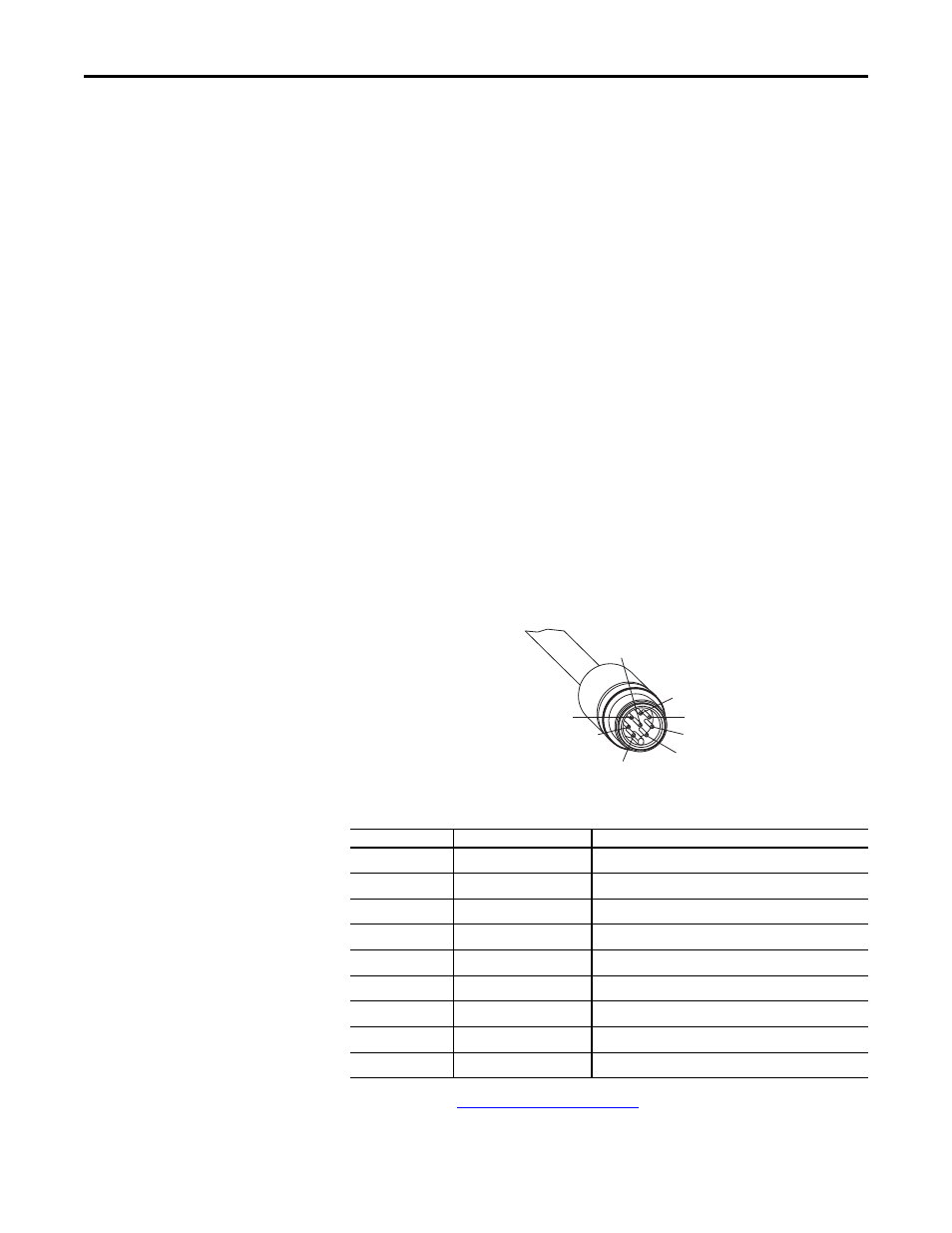
Round plug connector SafeZone Mini
Fig. 38: Round plug connector
SafeZone Mini
Pin assignment:
Table 9: Pin assignment of the
SafeZone Mini
Use the cordsets listed in
Table 18: Ordering information on page 65
to connect the SafeZone Mini.
8
4
1
2
3
6
7
5
Pin
Signal
Function
1
WF
Output for warning field 1
2
+24V DC
Supply voltage SafeZone Mini
3
I/O1
Universal I/O
4
I/O2
Universal I/O
5
OSSD1
Output signal switching device
6
OSSD2
Output signal switching device
7
0V DC
Supply voltage
8
FE/shield
Functional earth/shield
Housing
FE/shield
Functional earth/shield