Field sets – Rockwell Automation 442L-SFZNMN SafeZone Mini Safety Laser Scanner User Manual User Manual
Page 22
20
Rockwell Automation Publication 10000337275 Ver 01—October 2014
Chapter 4
Configurable functions
Field sets
Configuring the protective field and warning field
With the aid of the SCD software you can configure the field set, which comprises a protective field
and two warning
fields
. During this process you configure the shape and size of the protective and warning fields. You can realize any
field shape required.
Fig. 9: Creating a field set in the SCD software
Note
The area to be monitored is scanned radially by the SafeZone Mini. The SafeZone Mini cannot see through objects during
this process. The area behind objects that are in the area to be monitored (pillars, grilles, etc.) can thus not be monitored.
Protective fields and warning field can cover up an angle of up to 270° and have different radial scanning ranges
depending on the resolution configured (see Chapter 4, “Resolution” on page 16).
Check the protective fields configured!
Prior to commissioning the machine or vehicle, check the configuration of the protective fields using the instructions in
Chapter 9, “Commissioning” on page 47 and using the “Checklist” on page 70.
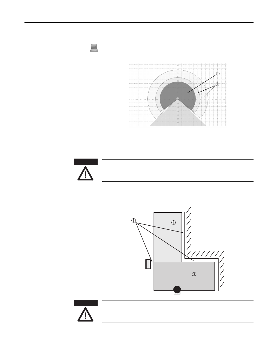
Note
If the protective field
or the warning fields stretch as far as a wall or another object (pillar, neighboring machine,
shelf), there should be a distance of 100 mm (3.94 in.) between the protective field or warning field and the object to
prevent false triggering
.
Fig. 10: Configuring protective
field and warning field
Secure unprotected areas!
If it is possible to access a narrow strip between the protective field and a wall or another object, you must protect this
strip using additional measures (e.g. fence or floor protection).
ATTENTION
ATTENTION