Wiring diagram, In603 – Yamato Scientific IN803 Low Temperature Incubators User Manual
Page 64
60
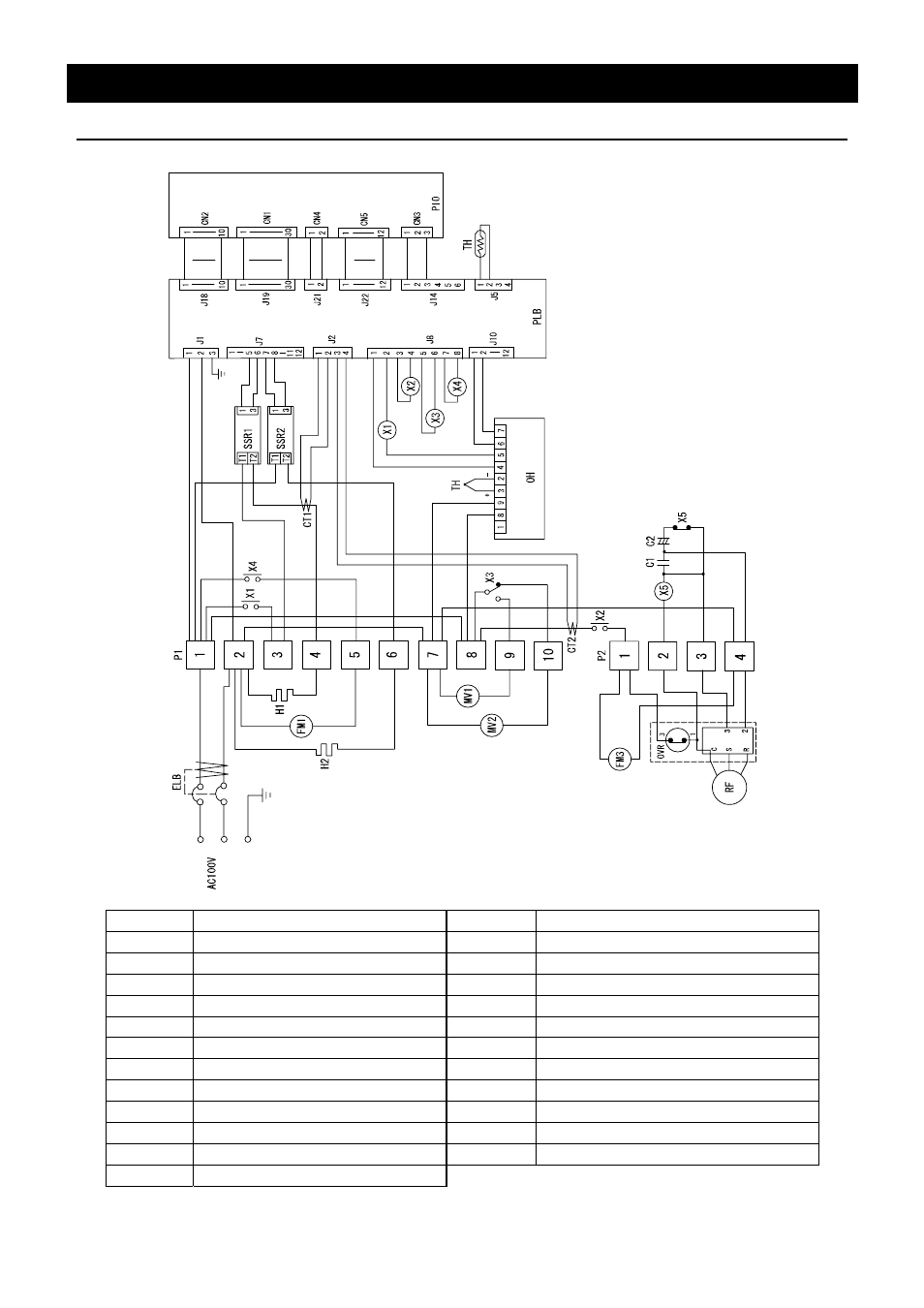
Wiring Diagram
IN603
J
1
J
1
Symbol
Part name
Symbol
Part name
ELB Earth
leakage
breaker
TH Temperature
sensor
1, 2
Terminal block
OH
Independent overheating prevention device
H1
Heater (internal)
SSR1, 2
Solid-state relay
H2
Heater (door)
PLB
PLANAR board
FM1
Fan motor (internal)
PIO
Display circuit board
FM3
Fan motor (refrigerator)
CT1, 2
Current transformer
MV1
Solenoid valve (defrost)
OVR
Overload relay
MV1
Solenoid valve (returning tube)
C1
Operation condenser
X1
Relay (internal heater)
C2
Starting condenser
X2
Relay (refrigerator)
X5
Starting relay
X3
Relay (solenoid valve)
RF
Refrigerator
X4 Relay
(fan)
This manual is related to the following products: