SDC 45 SERIES ELECTRIC STRIKES User Manual
Page 3
P:\INSTALLATION INST\ELECTRIC STRIKES\INST-45\INST-45.vsd REV K 12-13 Page 3
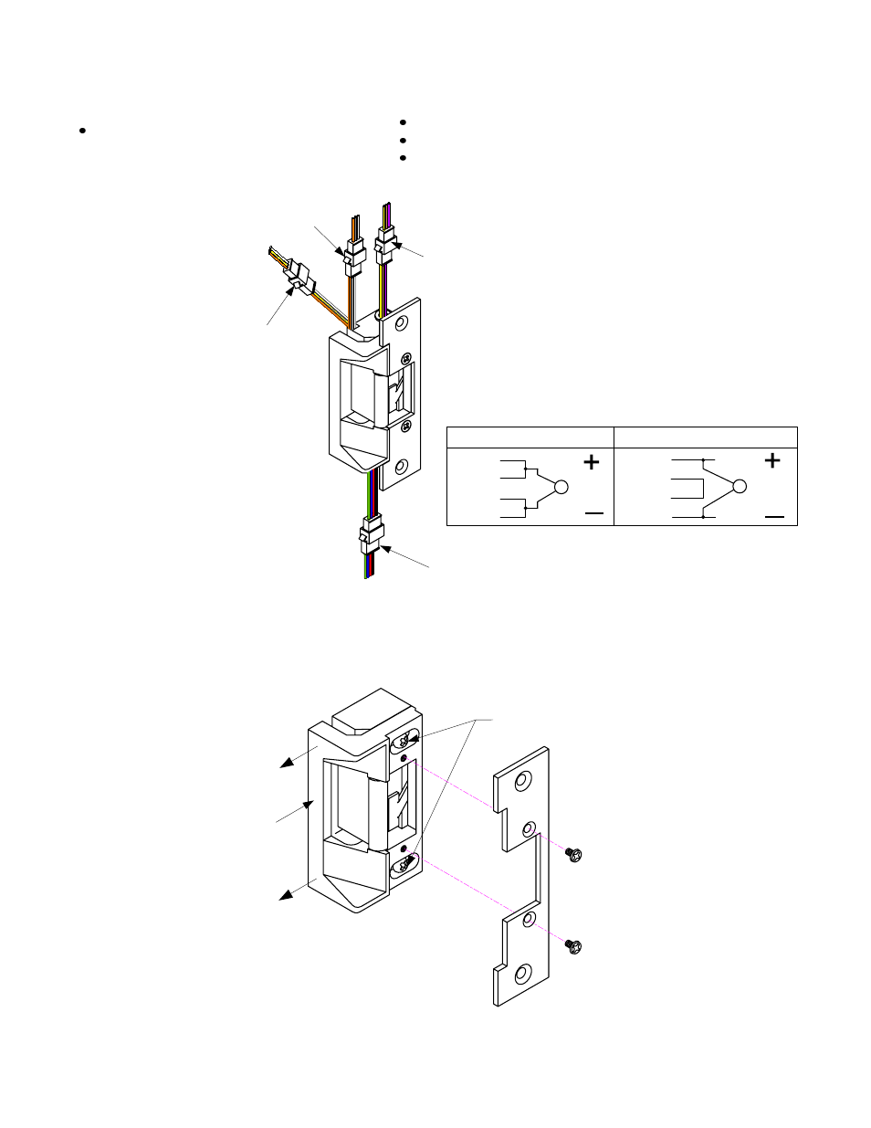
Horizontal Adjustment
Remove Faceplate. Loosen Horizontal Adjustment Screws and slide Die Cast
Body out as needed. Retighten Adjustment Screws and replace Faceplate.
Horizontal Adjustment
Screws
Die Cast Body
Keeper/Deadlocked: Purple – COM
Brown - N/O
Yellow - N/C
Latch Status: Orange - COM
White - N/O
Grey - N/C
Solenoid: Black, Red, Blue & Green
Electrical Data:
Dual Voltage: 200/100mA @ 12/24VDC
140/70mA @ 12/24VAC
Monitoring:
Latch Status: SDPT, dry 3Amp @ 30V (standard)
Keeper Closed and Deadlocked (standard)
Keeper Open/Closed Status: SPDT, Dry 3Amp @ 30V
(optional)
Keeper-Open/Closed:
Wht/Blk – COM
Yel/Blk - N/O
Org/Blk - N/C
The electric door strike shall be
installed in such a way as not to impair
the operation of an emergency exit or
panic hardware mounted on the door.
Wire leads must not be connected to
conductors larger than18AWG
Notes:
Red
Black
Blue
Green
Red
Black
Blue
Green
12V
24V
MOV
MOV
- S6100 SERIES REVERSIBLE PANIC/FIRE EXIT (23 pages)
- E5 Series Access Control System (30 pages)
- 918 EntryCheck (6 pages)
- 920P EntryCheck (8 pages)
- 921P EntryCheck (9 pages)
- 920 EntryCheck (8 pages)
- 295 Programmable Cabinet Lock (5 pages)
- E75 STANDALONE ELECTRONIC LOCKSET (6 pages)
- E72K-A CIVIC SERIES 160 User Electronic Digital Door Lock (7 pages)
- Z7200 CYLINDRICAL LOCK (4 pages)
- 7500 SERIES HiTower Z, S, I, D, P & T (2 pages)
- R7500 HiTower SCHLAGE L9080 MORTISE LOCK (2 pages)
- Z7835 SERIES MORTISE LOCK (10 pages)
- Z7800 SERIES MORTISE LOCK (7 pages)
- SK-L90 FIELD ELECTRIFICATION KIT SCHLAGE L9000 MORTISE LOCKSET (1 page)
- LR100VDK ELECTRIC LATCH RETRACTION DEVICE KIT 9975 (3 pages)
- LRVD1R PUSH PAD (REQUEST-TO-EXIT) SWITCH KIT VON DUPRIN 98/99-33 SERIES (1 page)
- LR100VDK-EM-22 ELECTRIC LATCH RETRACTION EXTERNAL MODULE VON DUPRIN 22 & 2227 (3 pages)
- LR100VDK-22 ELECTRIC LATCH RETRACTION DEVICE KIT VON DUPRIN 22 & 2227 (3 pages)
- LR100YDK YALE ELECTRIC LATCH RETRACTION DEVICE KIT 7210 (1 page)
- LR100DMK DOR-O-MATIC ELECTRIC LATCH RETRACTION DEVICE KIT 1590 (1 page)
- LR100CRK CORBIN/RUSSWIN ELECTRIC LATCH RETRACTION DEVICE KIT ED5800 (1 page)
- LR100PDK ELECTRIC LATCH RETRACTION DEVICE KIT 5200 (1 page)
- LRPD2L LATCH SWITCH KIT-VERTICAL ROD PHI/STANLEY 2000 SERIES (1 page)
- LR100K2K (K2) ELECTRIC LATCH RETRACTION DEVICE KIT QED124 (1 page)
- LR100IDCK ELECTRIC LATCH RETRACTION DEVICE KIT (1 page)
- LRCR1L LATCH SWITCH KIT CORBIN/RUSSWIN EXIT DEVICES (1 page)
- LR100HK-EM (Hager) EXTERNAL ELECTRIC LATCH RETRACTION DEVICE KIT (2 pages)
- LR100SGK ELECTRIC LATCH RETRACTION DEVICE KIT SARGENT 8600, 8700 & 8800 (1 page)
- LR100SGK-EM ELECTRIC LATCH RETRACTION DEVICE KIT SARGENT 8600, 8700 & 8800 (2 pages)
- LRSG1R REQUEST-TO-EXIT ELR SWITCH KIT SARGENT (1 page)
- LR100FAK FALCON(Dor-O-Matic) ELECTRIC LATCH RETRACTION KIT 1690 (1 page)
- LR100FRK FALCON IR SERIES ELECTRIC LATCH RETRACTION KIT 24-R, 24-V, 24-C (1 page)
- LR100ARK ADAMS RITE ELECTRIC LATCH RETRACTION DEVICE KIT VERTICAL ROD EXIT DEVICE 3100 (1 page)
- LR100ARK ADAMS RITE ELECTRIC LATCH RETRACTION DEVICE KIT RIM EXIT DEVICE 3700 (1 page)
- LR100DXK DETEX ELECTRIC LATCH RETRACTION DEVICE KIT 10, 20, 40, 50, 60 & 80 SERIES (2 pages)
- LR100AWK ELECTRIC LATCH RETRACTION DEVICE KIT ARROW S1150, S1250 (1 page)
- LRCR1R SWITCH KIT FOR CORBIN RUSSWIN E4000, E5000 (1 page)
- LRY1L EXIT DEVICE LATCH SWITCH KIT (1 page)
- LRY1R REX STATUS KIT 7000 SERIES YALE DEVICES (1 page)
- LR100MBSK ELECTRIC LATCH RETRACTION KIT Q1100, QF1100 (1 page)
- LR100DHK ELECTRIC LATCH RETRACTION KIT DESIGN HARDWARE 1000R, 1000V (2 pages)
- Electric Power Transfer Door Loops (1 page)
- 350 NARROW LIINE EMLOCK (6 pages)
- E6200 SERIES MAGNETIC LOCK (4 pages)