Instruction sheet, For concrete installation, Prs.4tec – Prescolite AL-ALE User Manual
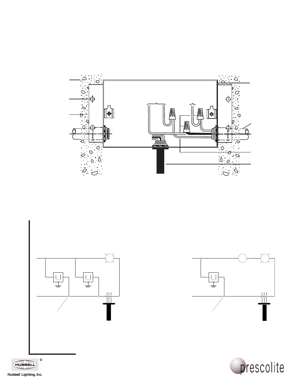
Page 3: Prescolite tollfree technical support, Hours: 8am - 5pm et, Housing installation fig. 5, Wiring diagram fig. 6
www
.prescolite.com
• Prescolite
TollFree
Technical Support
1.888.PRS.4TEC
• Hours: 8am - 5pm ET
101 Corporate Drive • Spartanburg, SC 29303
With representatives offices in principal cities throughout North America.
Copyright 2005, 06/05 revision, All Rights Reserved - Printed in U.S.A.
Part No. . . . . . . . . . . . . . . . . . . . . . . . . . . . . . . . .03217000
Instruction
Sheet
Concrete
Thermal
Protector
Wire Nut
(By Others)
Conduit
(By Others)
Housing
(Ground Wire)
(Socket Leads)
Housing Installation
Fig. 5
Adjustable
Mounting
Bracket (2)
Fastener (Nail)
(By Others)
(Blk.)
(Gnd.)
(Wht.)
For Concrete Installation
B
L
K
B
L
U
E
W
H
T
W
H
T
B
L
U
E
B
L
K
Thermal
Protector
Wire Nut
(By Others)
(Blk.)
Wiring Diagram
Fig. 6
(Wht.)
Wire Nut
(By Others)
120V
Supply
120V
Supply
(Blk.)
(Wht.)
SW
L
L
Thermal
Protector
Wiring Diagram
With Two Convenience Outlets
Wiring Diagram
With Switch and Convenience Outlet
NOTE: FOR POURED CONCRETE INSTALLATION DISCONNECT BLUE CONDUCTOR FROM LAMP
CONDUCTOR AND CONNECT LAMP CONDUCTOR DIRECTLY TO 120V SUPPLY. CAP OFF
THERMAL PROTECTOR AND LEAVE IN PLACE TO SEAL HOLE.