Prescolite AL-ALE User Manual
Instruction sheet, Installation instructions cat. no. al-ale series
Instruction
Sheet
www
.prescolite.com
• Prescolite
TollFree
Technical Support
1.888.PRS.4TEC
• Hours: 8am - 5pm ET
101 Corporate Drive • Spartanburg, SC 29303
With representatives offices in principal cities throughout North America.
Copyright 2005, 06/05 revision, All Rights Reserved - Printed in U.S.A.
Part No. . . . . . . . . . . . . . . . . . . . . . . . . . . . . . . . .03217000
IMPORTANT SAFETY INFORMATION. READ AND FOLLOW ALL SAFETY INSTRUCTIONS. Follow label information
and instructions concerning Wet or Damp Locations, installation near combustible materials, insulation, building materials,
and proper lamping. Do not install in areas subject to combustible vapors or gases. Before wiring to power supply and
during servicing or relamping, turn off power at fuse or circuit breaker. All servicing or relamping must be performed by
qualified service personnel. Product must be grounded to avoid potential electric shock or other potential hazard.
Product must be mounted in locations and at heights and in a manner consistent with its intended use, and in
compliance with the National Electrical Code and local codes. The use of accessory equipment not recommended by
the manufacturer or installed contrary to instructions may cause an unsafe condition. Do not block light emanating from
product in whole or part, as this may cause an unsafe condition. Do not allow items such as drapes, curtains, screens or
the like to come into contact with the product or to block light from the product, as this may cause an unsafe condition.
Instruction
Sheet
INSTALLATION INSTRUCTIONS
CAT. NO. AL-ALE Series
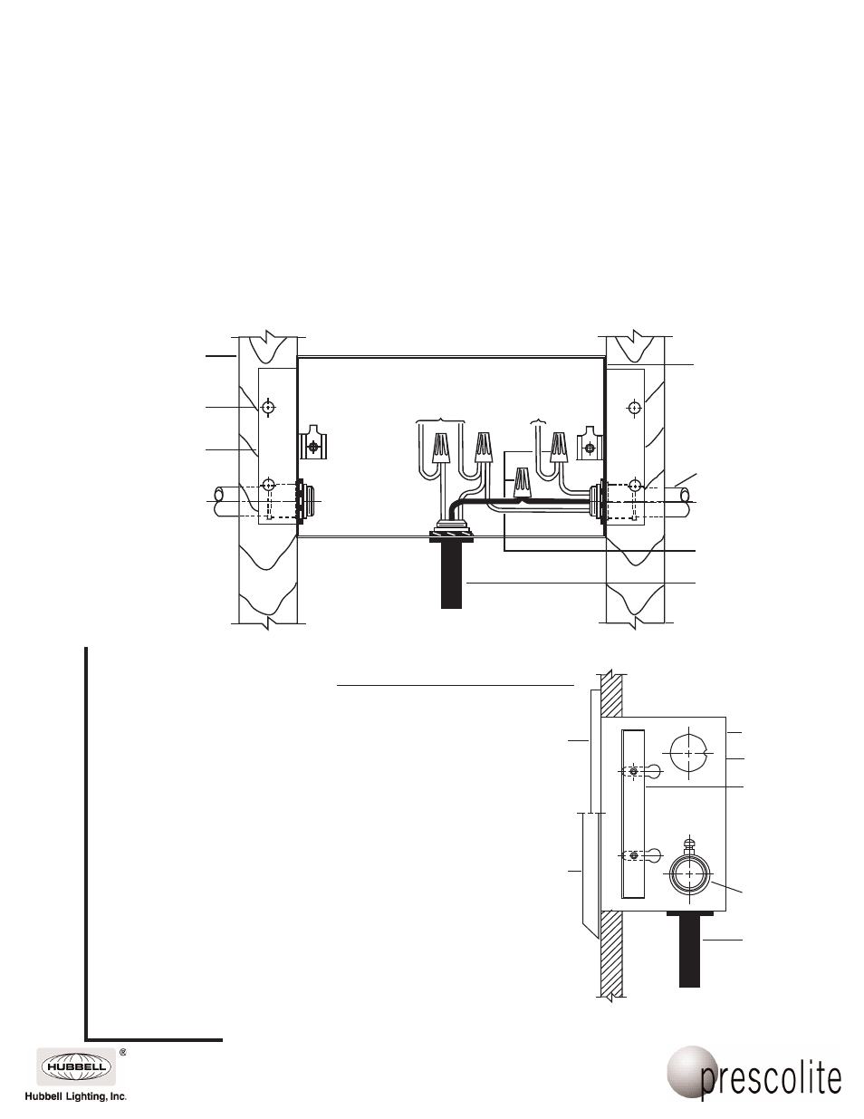
1. Install the housing by nailing the mounting
brackets on the housing to the frame support
as shown in Fig. 1 or frame in the housing
as desired for wet or drywall construction.
Adjust the mounting brackets to locate the
housing as required for profile style trims
Fig. 2
2. Install the conduit (by others) to align with
the 7/8" dia. knock-outs in the housing as
shown, remove the wing nut retaining the
socket mounting plate and lift out.
Support Frame
(By Others)
9690 Faceplate
(Wet or Drywall
Construction)
Profile Trims
Fig. 2
Thermal
Protector
Conduit
Entry
Adjustable
Mounting
Bracket (2)
Housing
Thermal
Protector
Wire Nut
(By Others)
Conduit
(By Others)
Housing
(Ground Wire)
(Socket Leads)
Housing Installation - Wet or Drywall
Fig. 1
Adjustable
Mounting
Bracket (2)
Fastener (Nail)
(By Others)
AL Faceplate
(Wet or Drywall
Construction)
(Blk.)
(Gnd.)
(Wht.)
(For Concrete Installation See FIG. 5)