Instruction sheet, Prs.4tec, Prescolite tollfree technical support – Prescolite AL-ALE User Manual
Page 2: Hours: 8am - 5pm et, Faceplate installation fig. 3, Wiring diagram fig. 4
B
L
K
B
L
U
E
W
H
T
W
H
T
B
L
U
E
B
L
K
www
.prescolite.com
• Prescolite
TollFree
Technical Support
1.888.PRS.4TEC
• Hours: 8am - 5pm ET
101 Corporate Drive • Spartanburg, SC 29303
With representatives offices in principal cities throughout North America.
Copyright 2005, 06/05 revision, All Rights Reserved - Printed in U.S.A.
Part No. . . . . . . . . . . . . . . . . . . . . . . . . . . . . . . . .03217000
Instruction
Sheet
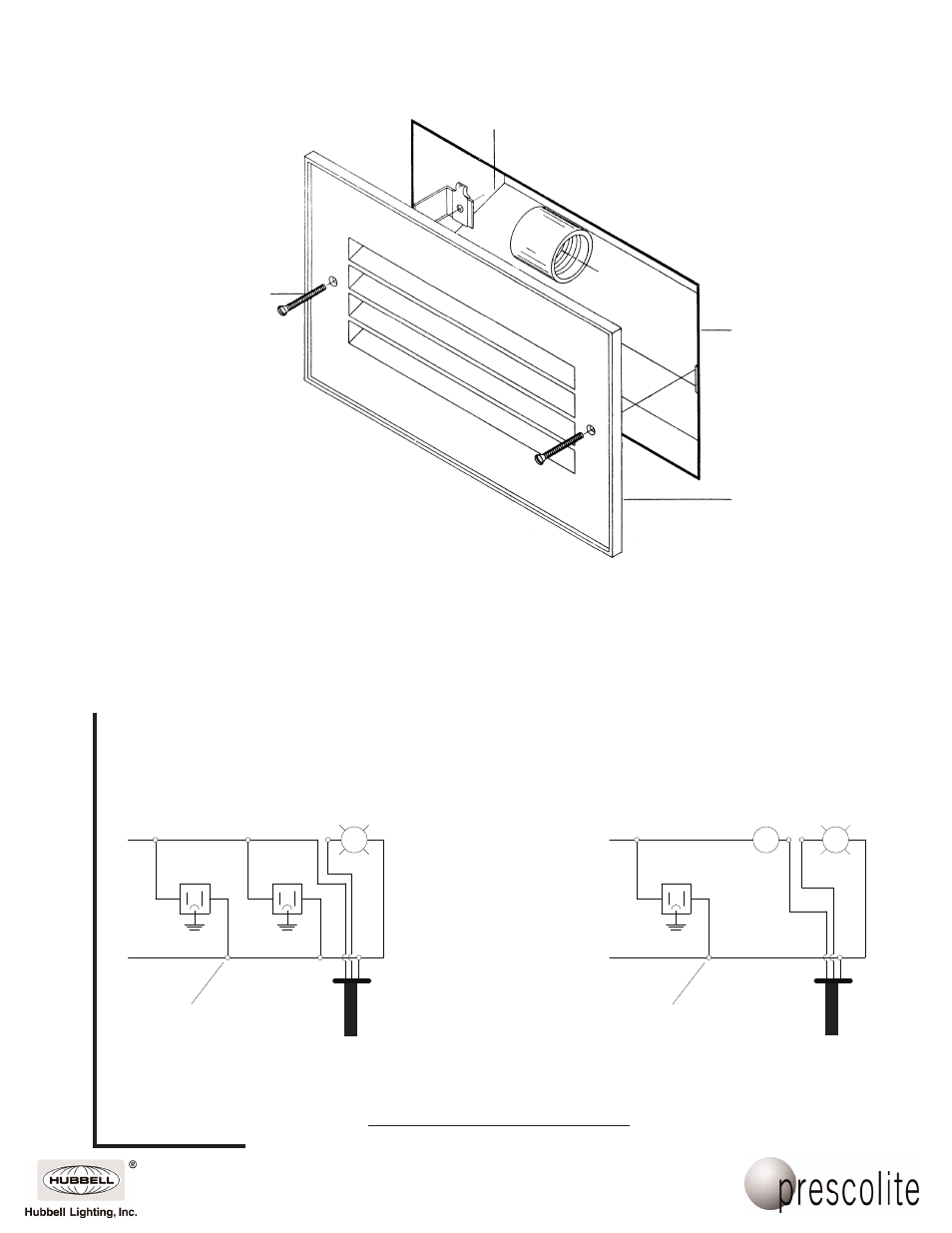
Socket Holder
Plate
Housing
(Installed)
Faceplate
AL-1
8-32 x 2" Oval
Head Screw (2)
Faceplate Installation
Fig. 3
3. For faceplates with switch and convenience outlets make supply connections per Fig. 4, (Fig. 6 for concrete).
Faceplates without switch or convenience outlets should be wired as shown in Fig. 1 (Fig. 5 for concrete).
Splice the supply ground to the ground wire on the socket mounting plate, replace the plate and install the
lamp.
4. Assemble the faceplate, (AL-1) to the housing as shown in Fig. 3 with two 8-32 x 2" screws provided in
packet. Faceplates AL-4, 5, 6 and Cat. No. 9690 are provided with a hinged access door for relamping.
Assemble the four faceplates by opening the access door and installing the two 8-32 x 1 3/8 screws thru the
mounting holes in the faceplate and into the retaining clips in the housing. Close access door.
(For Concrete Installation See FIG. 6)
Thermal
Protector
Wire Nut
(By Others)
(Blk.)
(Wht.)
Wire Nut
(By Others)
120V
Supply
120V
Supply
(Blk.)
(Wht.)
SW
L
L
Thermal
Protector
Wiring Diagram
With Two Convenience Outlets
Wiring Diagram
With Switch and Convenience Outlet
Wiring Diagram
Fig. 4