Sh e e t – Prescolite MC10LED CYLINDER CORD AND CABLE MOUNT User Manual
Page 4
In
s
tr
u
c
tio
n
S
h
e
e
t
Part No...........................................
With representatives offices in principal cities throughout North America.
Copyright , revision, All Rights Reserved - Printed in U.S.A.
701 Millennium Blvd • Greenville, SC 29607
w
w
w
.p
re
s
c
o
lit
e
.c
o
m
P
re
s
c
o
lit
e
T
o
ll
F
re
e
T
e
c
h
n
ic
a
l S
u
p
p
o
rt
1
.8
8
8
.P
R
S
.4
T
E
C
H
o
u
rs
: 8
a
m
-
5
p
m
E
T
93054545
2014
03/26/14
Fig. 8
SLIDE
HOUSING
CLOSED
PHILLIPS
SCREW
(1 OF 2)
LOCKING
SLOT
Fig. 7
POWER
CORD
PUCK
POWER
CORD
HOLE
CORD
GRIP
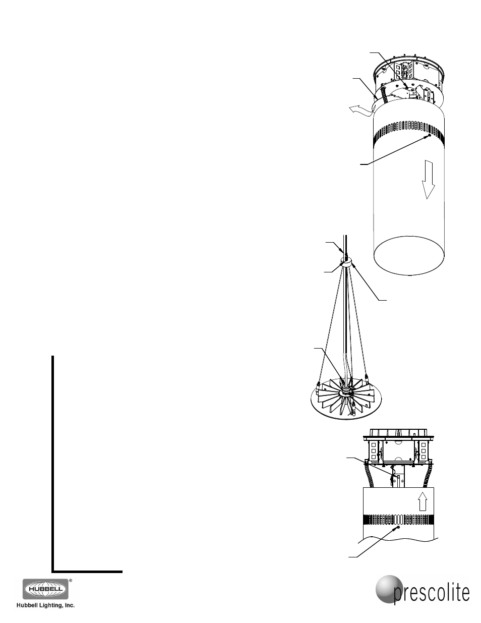
8. Carefully open the cylinder housing by loosening (do not
remove) the two Phillips screws on opposite sides of the
cylinder (near the vent slots) until the screws disengage from
the internal locking slots, and the cylinder housing is free to
slide down. Slide the outer cylinder housing open towards the
reflector (it should move about 7 inches from the top finned
casting) and tighten the two Phillips screws (Fig. 6).
9. Loosen the two thumbscrews holding the wiring compartment
cover closed, rotate the cover to free it, and carefully slide it
out of the way (there is a safety cable to hold it while the wiring
is being completed).
10. Feed the power cord through the hole in the puck assembly
and insert the end of the power cord through the cord grip and
into the cylinder wiring compartment (Fig. 7). Trim the power
cord to length, if needed. NOTE: If desired, tie the power cord
to the 20 foot cable with nylon cable ties every foot before
trimming the power cord to length! Strip the jacket from the
power cord and strip the end of each conductor 3/8ths of an
inch. Make the electrical connections in the fixture wiring
compartment. The line voltage (Black-Striped) conductor
connects to the two-position connector with the Red thermal
protector wire. The neutral (White-Striped) conductor attaches
to the empty position on the connector with the White wires.
Connect the ground (Green-Striped) conductor to the two-
position connector with the Green wire. Use the two extra
power cord conductors (Blue-Striped and Red-Striped) to
connect to the dimming control wires, if provided. Make sure to
follow the same connection colors as used in Step 3. Cap off
these conductors if not used.
CAUTION: When making these connections, be careful
that no stray strands of wire stick out of the connectors
that might cause electrical shorts!
CAUTION: Do not allow the weight of the fixture to be
supported by the power cord! The weight of the fixture
should be supported by the cable system alone!
11. After the electrical connections are completed, replace the
wiring compartment cover and tighten the thumbscrews to
complete the wiring at the fixture.
12. Once again loosen (do not remove) the two Phillips screws on
opposite sides of the cylinder until the cylinder housing is free
to slide. Slide the MC10LED outer cylinder housing upwards
until it seats on the finned casting.
CAUTION: Do not pinch any wires between the cylinder
housing and any other parts of the fixture!
Be sure the cylinder housing is completely seated, and tighten
the two Phillips screws to lock the cylinder housing in place.
NOTE: If the cylinder housing does not fully seat when closing,
you may need to loosen the screws a little more to slide it
closed. This will allow the ends of the screws to pass the
locking slots at the very end of the slide travel (Fig. 8).
KEEP THESE INSTALLATION INSTRUCTIONS!
Fig. 6
PHILLIPS
SCREW
(1 OF 2)
THUMBSCREW
(1 OF 2)
WIRING
COMPARTMENT
COVER
SLIDE
HOUSING
OPEN