Sh e e t – Prescolite MC10LED CYLINDER CORD AND CABLE MOUNT User Manual
Page 2
In
s
tr
u
c
tio
n
S
h
e
e
t
Part No...........................................
With representatives offices in principal cities throughout North America.
Copyright , revision, All Rights Reserved - Printed in U.S.A.
701 Millennium Blvd • Greenville, SC 29607
w
w
w
.p
re
s
c
o
lit
e
.c
o
m
P
re
s
c
o
lit
e
T
o
ll
F
re
e
T
e
c
h
n
ic
a
l S
u
p
p
o
rt
1
.8
8
8
.P
R
S
.4
T
E
C
H
o
u
rs
: 8
a
m
-
5
p
m
E
T
93054545
2014
03/26/14
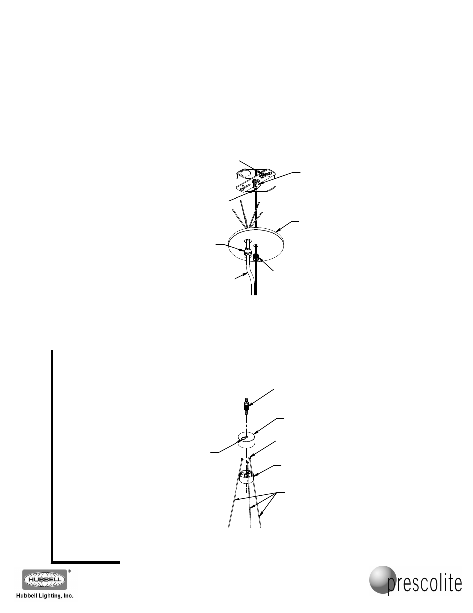
3. Lock the strain relief to the power cord with allowance for wiring connections, and thread the power cord
through the canopy wire hole (Fig. 3). Snap the cord assembly into the canopy. Make the ground connection
to the ground screw on the crossbar assembly and the Green-Striped ground conductor on the power cord.
Connect the line voltage to the Black-Striped conductor, the neutral to the White-Striped conductor. Make
any dimming control connections to the 2 extra conductors (Blue-Striped and Red-Striped, to be connected
in the fixture in the next steps – cap off these conductors if not used). Make all connections with properly
sized, UL listed connectors. Thread the 20 foot cable through the canopy center hole. Thread the 20 foot
cable through the barrel coupler, and slide it up to the canopy. Place the wiring and connections into the
junction box and push canopy up flush to the ceiling surface. Thread the barrel coupler onto the threaded
gripper body to retain the canopy. Tighten the cable gripper lock nut on the cable.
Fig. 4
PUCK TOP
HALF
PUCK BOTTOM
HALF
1/4-20
GRIPPER
BALL-STOP
ENDS
24 INCH
CABLES
CORD
OPENING
Fig. 3
POWER Cord
CORD
STRAIN
RELIEF
BARREL
COUPLER
CANOPY
GROUND
SCREW
4. Assemble the cable puck by dropping the ball-stop ends of the three 24 inch cables into the slots on the
puck bottom half (Fig. 4). Assemble the puck top half, making sure the cord opening in the top half lines up
with the one in the bottom half. Thread the ¼-20 gripper into the top center opening and tighten to hold the
puck assembly together.
THREADED
GRIPPER
BODY
GRIPPER
LOCK NUT