Sh e e t – Prescolite MC10LED CYLINDER CORD AND CABLE MOUNT User Manual
Page 3
In
s
tr
u
c
tio
n
S
h
e
e
t
Part No...........................................
With representatives offices in principal cities throughout North America.
Copyright , revision, All Rights Reserved - Printed in U.S.A.
701 Millennium Blvd • Greenville, SC 29607
w
w
w
.p
re
s
c
o
lit
e
.c
o
m
P
re
s
c
o
lit
e
T
o
ll
F
re
e
T
e
c
h
n
ic
a
l S
u
p
p
o
rt
1
.8
8
8
.P
R
S
.4
T
E
C
H
o
u
rs
: 8
a
m
-
5
p
m
E
T
93054545
2014
03/26/14
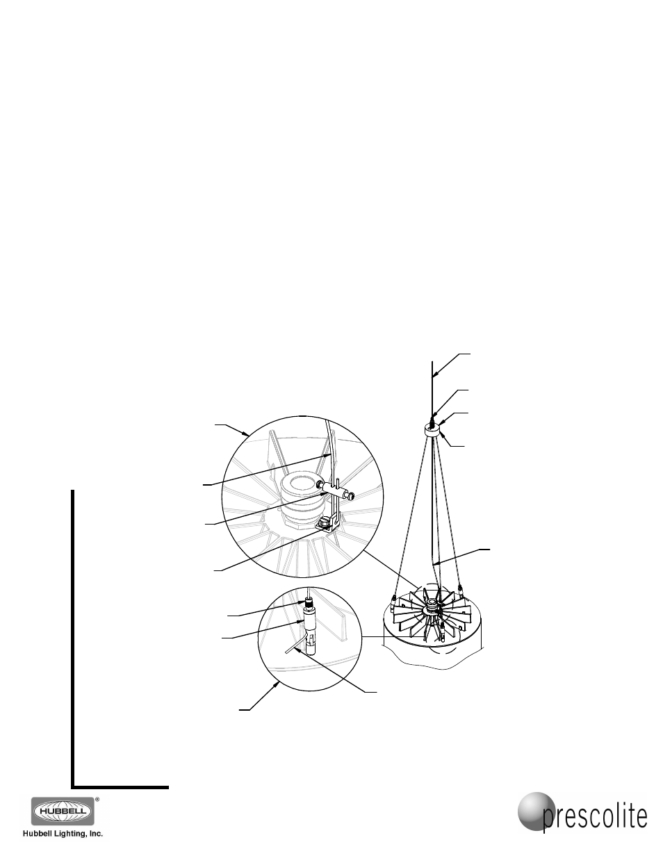
Fig. 5
LOCK NUT
PUCK
ASSEMBLY
SWIVEL
GRIPPER
(1 OF 3)
LOCK NUT
1/4-20
GRIPPER
20 FOOT
CABLE
CABLE
LOCKING
TUBE
SUPPORT TAB
20 FOOT
CABLE
1 INCH OF
CABLE
MINIMUM
SLACK IN
CABLE
BELOW
THE PUCK
5. Loosen the lock nuts on the 3 swivel grippers on the top casting of the cylinder (Fig. 5). Insert the end of each of
the 24 inch cables from the puck assembly into a corresponding swivel gripper on the top casting. The cables
need to protrude through the grippers at least 1 inch (VIEW A). Tighten the lock nuts. (These cables can be
adjusted later in the installation.)
6. Loosen the lock nut on the ¼-20 gripper on the puck assembly and slide the puck assembly and fixture onto the
20 foot cable to the height the fixture is intended to hang. Loosen the locknuts on the three 24 inch cables and
adjust the fixture and the puck to level the fixture and set the cable lengths needed for the installation.
NOTE: The fixture weight will need to be lifted and supported so the grippers will release to allow adjustment of
the cables. After adjustment to the final position, tighten the lock nuts on all the grippers.
7. After the adjustment of the cable lengths is complete, slide the end of the 20 foot cable through one side of the
cable locking tube, loop the remaining length through the support tab hole, and then back through the other side
of the cable locking tube (VIEW B). Leave a couple of inches of slack in the 20 foot cable below the puck (this
cable should not be holding the fixture weight below the puck) and tighten the two screws on either side of the
cable locking tube. Trim the ends of the cables if needed using the proper cable cutting tool (such as a FELCO
C7). To prevent fraying of the cut cable ends, use a drop of superglue or solder the cable end.
CAUTION: Always leave at least 1 inch of cable beyond the body of the grippers.
VIEW B
VIEW A