2 configuring dip-switches, 1 board-mounted bank 1 settings, Board-mounted bank 1 settings – Omnitron Systems Technology iConverter 2FXM User Manual User Manual
Page 6
3.2
CONFIGURING DIP-SWITCHES
PI
SA
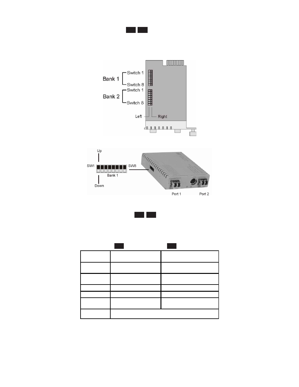
The 2FXM plug-in module has two board-mounted DIP-switches. The standalone unit has one bank of
DIP-switches. The locations of the DIP-switches are illustrated on below.
DIP-switch Locations
3.2.1
Board-Mounted Bank 1 Settings
PI
SA
DIP-switch Bank 1 is available on both the plug-in and standalone modules. The table indicates the position
of the switch; Left/Down or Right/Up. As indicated in the DIP-switch location diagram, Left and Right
refers to the plug-in module and Down and Up refers to the standalone module.
PI
(Left/Right)
SA
(Up/Down)
Switch
Left/Down
(Factory Default)
Right/Up
SW1
Off:
Pause Disable
On:
Pause Enable
SW2
FDX:
Fiber Port 1Full-Duplex
HDX:
Fiber Port 1 Half-Duplex
SW3
Reserved
Reserved
SW4
Reserved
Reserved
SW5
FDX:
Fiber Port 2 Full-Duplex
HDX:
Fiber Port 2 Half-Duplex
SW6 - SW8
See Link Mode DIP-Switch Table in Section 3.2.1.6
3.2.1.1
SW1 - Pause Disable/Enable “Off/On”
When the Pause Enable DIP-switch is “Off” position (factory default), the 2FXM disables the fiber ports’
ability to send and receive Pause frames during network congestion. Setting this DIP-switch to the“On”
position, enables the 2FXM to receive Pause frames from its link partner. This enables the 2FXM to stop
Page 6