Omnitron Systems Technology iConverter 2GXT Standalone User Manual
Iconverter, 2gxt standalone module user manual
iConverter
2GXT
Standalone Module User Manual
Product Overview
The iConverter 2GXT is a standalone, unmanaged media converter with two 10/100/1000 RJ-45
copper ports and two Small Form Pluggable (SFP) fiber ports. The 2GXT can be deployed as a dual-
channel media converter that provides two independent copper-to-fiber converters in one compact
module, or deployed as a four-port switch with dual fiber ports that can be configured to provide 1:1
uplink protection with less than 50ms switchover.
The 2GXT supports both 100BASE-X and 1000BASE-X SFPs to provide flexible connectivity to Fast
Ethernet or Gigabit networks.
Installation Procedure
1) Configure DIP-switches
2) Install Standalone Module and Connect Cables
3) Verify Operation
1) CONFIGURE DIP-SWITCHES
DIP-SWITCH BANK 1
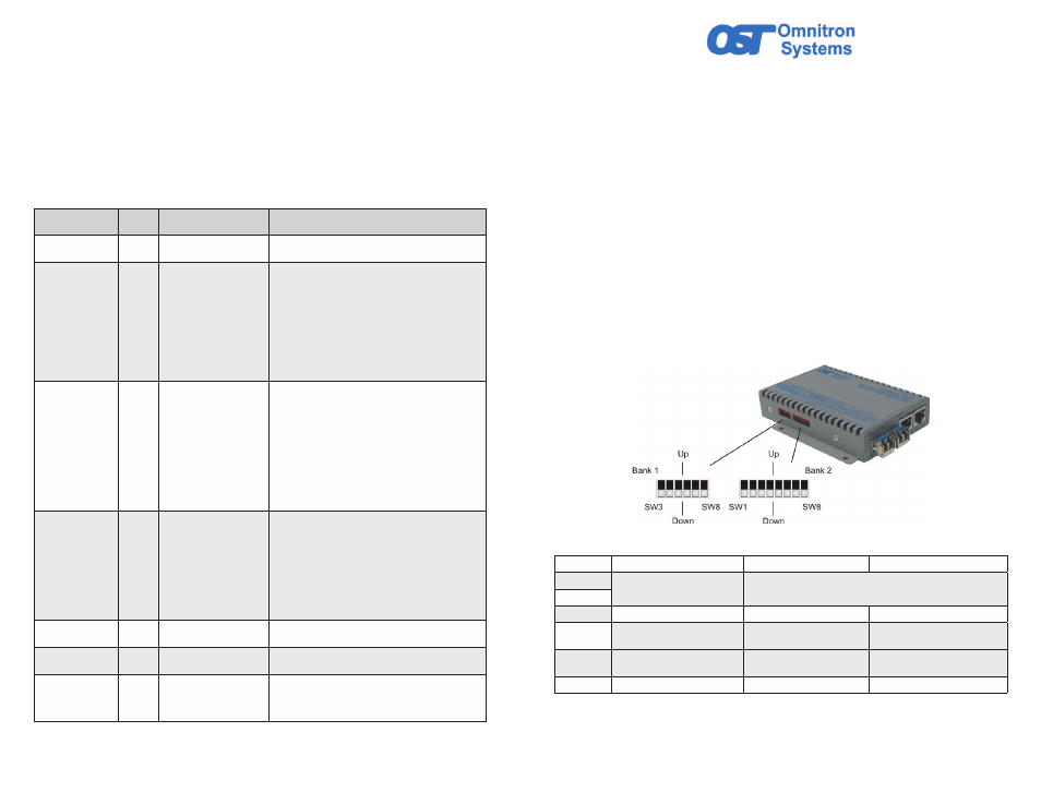
The location of the DIP-switches is shown in Figure 1. The functions of DIP-switch Bank 1 are
outlined in Figure 2.
Figure 1: DIP-switch Locations
Switch
Function
DOWN (Default)
UP
SW3
Operational Modes
See Figure 3
SW4
SW5
Pause
Off
On
SW6
Link Propagate Fiber to Copper
Link Segment
Link Propagate Fiber to Copper
P1 to P3 and P2 to P4
SW7
Link Propagate Copper to Fiber
Link Segment
Link Propagate Copper to Fiber
P3 to P1 and P4 to P2
SW8
Reserved
Off
On
Figure 2: DIP-switch BANK 1 Definitions
c.
Connect the UTP port via a Category 5 or better cable to a 10BASE-T, 100BASE-TX or
1000BASE-T Ethernet device.
d.
Connect an appropriate multimode or single-mode fiber cable to the fiber port of the installed
module. It is important to ensure that the transmit (TX) is attached to the receive side of the
device at the other end and the receive (RX) is attached to the transmit side. Single-fiber (SF)
media converter models operate in pairs. The TX wavelength must match the RX wavelength
at the other end and the RX wavelength must match the TX wavelength at the other end.
3) VERIFY OPERATION
Verify the correct LED is illuminated based on the configuration of the port. Figure 6 indicates the
operation of the port based on the illuminated LEDs. If the 100 LED is illuminated, the port is operating
at 100Mbps. If the 1000 LED is illuminated, the port is operating at 1000Mbps and if the 100 and
1000 LEDs are illuminated, the port is operating at 10Mbps.
LED Function
“Legend”
Color
OFF State
ON/Blinking State
Power
“PWR”
Green
No power
Module has power
P1/P2 Activity
“100”
Green/
Amber
Port not linked at 100M
Solid Green: Port linked at 100M
Blinking Green (10Hz): Data activity
Blinking Green (1Hz): Port linked and in redundant
standby mode
Solid Amber: Port linked and transceiver has detected
a DDMI alarm
Blinking Amber (10Hz): Data activity and transceiver
has detected an alarm
Blinking Amber (1Hz): Port linked and transceiver
has detected an alarm (redundant standby mode) or
Port is operating at 100M and receiving FEFI
P1/P2 Activity
“1000”
Green/
Amber
Port not linked at 1000M
Solid Green: Port linked at 1000M
Blinking Green (10Hz): Data activity
Blinking Green (1Hz): Port linked and in redundant
standby mode
Solid Amber: Port linked and transceiver has detected
a DDMI alarm
Blinking Amber (10Hz): Data activity and transceiver
has detected a DDMI alarm
Blinking Amber (1Hz): Port linked and transceiver
has detected a DDMI alarm (redundant standby
mode) or Port is operating at 1000M and receiving
AN_Remote_Fault
P1/P2 Activity
“100” and “1000”
Green
Port not linked at 10M
Solid Green: Port linked at 10M
Blinking Green (10Hz): Data activity
Blinking Green (1Hz): Port linked and in redundant
standby mode
Solid Amber: Port linked and transceiver has detected
a DDMI alarm
Blinking Amber (10Hz): Data activity and transceiver
has detected a DDMI alarm
Blinking Amber (1Hz): Port linked and transceiver
has detected a DDMI alarm (redundant standby mode)
P3/P4 Activity
“100”
Green/
Amber
Port is not linked at 100M
Solid Green: Port is linked at 100M
Blinking Green (10Hz): Data activity
P3/P4 Activity
“1000”
Green/
Amber
Port is not linked at 1000M Solid Green: Port is linked at 1000M
Blinking Green (10Hz): Data activity
P3/P4 Activity
“100 and 1000”
Green/
Amber
Port is not linked at 10M
Solid Green: Port is linked at 1000M
Blinking Green (10Hz): Data activity
Blinking Amber (1Hz): Port receiving AN_Remote_
Fault
Figure 6: LED Indicators
040-08484-001A 7/14
Page 1
Omnitron Systems Technology 38 Tesla, Irvine, CA 92618
949.250.6510 tel * 949.250.6514 fax * www.omnitron-systems.com