Omnitron Systems Technology iConverter 3-Port GM4 User Manual
Iconverter
iConverter
3-Port GM4 Network Interface Device
Quick Start Guide
PRODUCT OVERVIEW
This document describes the basic installation and configuration of the 3-Port GM4 standalone
modules.
The GM4 features one or two SFP ports, one or two UTP ports and a RS-232 Serial Console
Port. The SFP ports support SERDES 100/1000BASE-X SFP fiber and Omnitron approved
SGMII 10/100/1000BASE-T copper transceivers.
NOTE: When using third party 100BASE-FX and unapproved SGMII SFPs, the port must
be manually configured using the Command Line Interface (CLI). Interface settings can be
changed using the portattribute command. For more information including the complete
User Manual on the 3-Port GM4 modules, access Omnitron’s registration page and register
the product:
http://www.omnitron-systems.com/forms/product_registration.php
INSTALLATION PROCEDURE
1) Configure DIP-Switches
2) Install Standalone Module and Connect Cables
3) Configure Module via Command Line Interface
4) Verify Operation
1) CONFIGURE DIP-Switches
DIP-SWITCH BANK 1
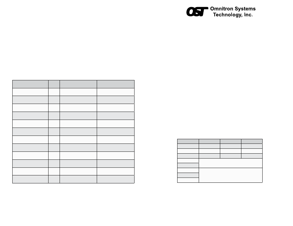
The function of DIP-switch Bank 1 is outlined in Figure 1 below.
Switch Position
Legend
Down (Default)
Up
1
P1 AN/MAN
AN
MAN
2
P2 AN/MAN
AN
MAN
3
P3 AN/MAN
AN
MAN
4
Port Redundancy (See Figure 3)
5
6
Link Modes (See Figure 4)
7
8
Figure 1: DIP-switch Bank 1
The location of the DIP-switch is illustrated in Figure 2 on the next page.
SW1 - SW3: P1, P2 and P3 AUTO/MANUAL NEGOTIATION “AN/MAN”
When these DIP-switches are in the Down “AN” position (factory default), the corresponding
port automatically determines the duplex and pause modes of the connected device. If the
3) CONFIGURE MODULE VIA COMMAND LINE INTERFACE
To access the Menu-Driven Interface, connect the GM4 RS-232 Serial Console Port to the
COM port of a computer equipped with terminal emulation software such as HyperTerminal.
The Console Port (DCE) is a mini DIN-6 female connector which can be changed to a
DB-9 connector with the included adapter. The GM4 Console Port is a standard RS-232
asynchronous serial interface.
Start HyperTerminal and select the correct COM Port in the HyperTerminal “Connect To:”
window. Set the serial port to the following:
Bits Per Second
57,600
Stop Bits
1
Data Bits
8
Parity
NONE
Hardware Flow Control
NONE
The Menu-Driven Interface enables detailed configuration of the module.
4) VERIFY OPERATION
Once the module has been installed and configured per steps 1 - 3, verify the module is
operational by viewing the LED indicators.
LED Function
“Legend”
Color
OFF State
ON/Blinking State
Power
“PWR”
Green
No power
ON: Module has power
P1 Link Activity
“100”
Green
Port not linked at 100M
ON: Port linked at 100M
Blinking: Data activity
P1 Link Activity
“1000”
Green
Port not linked at 1000M
ON: Port linked at 1000M
Blinking: Data activity
P1 Link Activity
“100” and “1000”
Green
Port not linked at 10M
ON: Port linked at 10M
Blinking: Data activity
P2 Link Activity
“100”
Green
Port not linked at 100M
ON: Port linked at 100M
Blinking: Data activity
P2 Link Activity
“1000”
Green
Port not linked at 1000M
ON: Port linked at 1000M
Blinking: Data activity
P2 Link Activity
“100” and “1000”
Green
Port not linked at 10M
ON: Port linked at 10M
Blinking: Data activity
Test/Alarm
“Tst/Alm”
Green
Reserved
Reserved
Management Mode
“Msr/Slv”
Green
N/A
ON: Master (normal)
5 Hz Blinking: Secure Slave
P3 Link Activity
“100”
Green
Port not linked at 100M
ON: Port linked at 100M
Blinking: Data activity
P3 Link Activity
“1000”
Green
Port not linked at 1000M
ON: Port linked at 1000M
Blinking: Data activity
P3 Link Activity
“100” and “1000”
Green
Port not linked at 10M
ON: Port linked at 10M
Blinking: Data activity
Figure 5: LED Indicators
040-8970R-001B 2/12
Page 1
Omnitron Systems Technology * 140 Technology Dr. * Irvine, CA 92618
949.250.6510 tel * 949.250.6514 fax * www.omnitron-systems.com