Omnitron Systems Technology iConverter GX/T2 Standalone Module User Manual
Iconverter, Gx/t2 standalone module user manual
iConverter
GX/T2
Standalone Module User Manual
Product Overview
The GX/T2 is a 10/100/1000BASE-T UTP to 100BASE-FX or 1000BASE-X modular fiber media
converter that supports jumbo frames up to 10,240 bytes. The GX/T2 features Small Form Pluggable
(SFP) transceivers that support both 100BASE-FX and 1000BASE-X for interoperability with Fast
Ethernet and Gigabit fiber equipment.
Installation Procedure
1) Configure DIP-switches
2) Install Standalone Module and Connect Cables
3) Verify Operation
1) CONFIGURE DIP-SWITCHES
DIP-SWITCH BANK 1
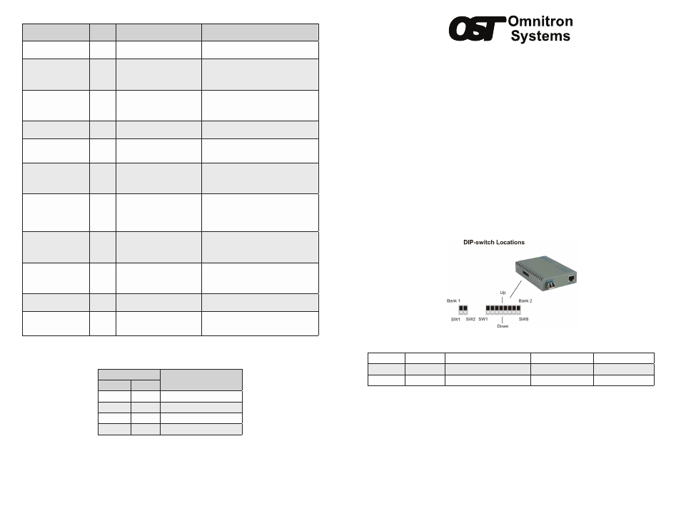
The location of the DIP-switches is shown in Figure 1. The functions of DIP-switch Bank 1 are
outlined in Figure 2.
SW1 and SW2: Reserved
These DIP-switches are reserved and must be in the Down (default) position.
Figure 1: DIP-switch Locations
Switch
Legend
Function
DOWN (Default)
UP
SW1
OPT1
Reserved
Off
On
SW2
OPT2
Reserved
Off
On
Figure 2: DIP-switch BANK 1 Definitions
DIP-SWITCH BANK 2
The functions of DIP-switch Bank 2 are outlined in Figure 3.
SW1: Port 1 “Auto/100”
This DIP-switch configures the speed of the transceiver installed in Port 1. If the DIP-switch is in the
Down “Auto” (default) position, the port detects the data rate of the transceiver installed and operates
at 100M or 1G accordingly. If the DIP-switch is in the Up “100” position, the port is expecting a 100M
capable transceiver to be installed.
NOTE: SW1 is not available for fixed fiber models. The fiber port is always set to 1000.
LED Function
“Legend”
Color
OFF State
ON/Blinking State
Power
“PWR”
Green
No power
Module has power
P1 Link Activity
1
“100”
Green/
Amber
Port not linked at 100M
Solid Green: Port linked at 100M
Blinking Green: Data activity
Blinking Amber: Port is operating at 100M
and receiving FEFI
P1 Link Activity
“1000”
Green/
Amber
Port not linked at 1000M
Solid Green: Port linked at 1000M
Blinking Green: Data activity
Blinking Amber: Port is operating at 1000M
and receiving a remote fault
P1 Link Activity
1
“100” and “1000”
Green
Port not linked at 10M
Solid Green: Port linked at 10M
Blinking Green: Data activity
P1 Duplex
“P1 FDX”
Green
Port is configured for half duplex
per DIP-switch or resolved by
auto-negotiation
Solid Green: Port is configured for full
duplex operation per DIP-switch or resolved
by auto-negotiation
P1 SFP DMMI Alarm
1
“P1 Stat”
Green/
Amber
Installed transceiver does not
support digital diagnostics or no
transceiver installed
Solid Green: Installed transceiver supports
digital diagnostics and no alarm detected
Solid Amber: Installed transceiver has
detected an alarm
P2 Negotiation Mode
“P2 AN”
Green
Port is configured for Manual
operation
Solid Green: Port is configured for Auto-
negotiation
Blinking Green: Port is configured for
auto-negotiation but has not completed the
process with attached link partner
P2 Link Activity
“100”
Green/
Amber
Port not linked at 100M
Solid Green: Port linked at 100M
Blinking Green: Data activity
Blinking Amber: Port receiving a remote
fault at 100Mbps
P2 Link Activity
“1000”
Green/
Amber
Port not linked at 1000M
Solid Green: Port linked at 1000M
Blinking Green: Data activity
Blinking Amber: Port receiving a remote
fault at 1000Mbps
P2 Link Activity
“100” and “1000”
Green
Port not linked at 10M
Solid Green: Port linked at 10M
Blinking Green: Data activity
P2 Duplex
“P2 FDX”
Green
Port is configured for half duplex
per DIP-switch or resolved by
auto-negotiation
Solid Green: Port is configured for full
duplex operation per DIP-switch or resolved
by auto-negotiation
Figure 6: LED Indicators
1
LEDs are not installed on the fixed fiber models
LED Legend/State
Link Speed
“1000”
“100”
OFF
OFF
Port not linked
OFF
ON
Port linked at 100Mbps
ON
OFF
Port linked at 1000Mbps
ON
ON
Port linked at 10Mbps
Figure 7: Port Speed LED Indicators
040-8520N-001B 11/13
Page 1
Omnitron Systems Technology 38 Tesla, Irvine, CA 92618
949.250.6510 tel * 949.250.6514 fax * www.omnitron-systems.com