Omnitron Systems Technology iConverter 2-Port SFP to SFP GM4 User Manual
Iconverter
iConverter
2-Port SFP to SFP GM3
Network Interface Device
Quick Start Guide
PRODUCT OVERVIEW
This document describes the basic installation
and configuration of the 2-Port SFP to SFP GM3
standalone modules.
For more information including the complete User
Manual on the 2-Port SFP to SFP GM3 modules,
access Omnitron’s registration page and register
the product:
http://www.omnitron-systems.com/forms/product_registration.php
INSTALLATION PROCEDURE
1) Configure DIP-Switches
2) Install Standalone Module and Connect Cables
3) Configure Module via Command Line Interface
4) Verify Operation
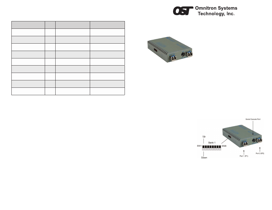
1) CONFIGURE DIP-Switches
DIP-SWITCH BANK 1
SW1 and SW2: P1 and P2 AUTO/MANUAL NEGOTIATION “AN / Man”
When this DIP-switch is in the “AN”
position (factory default), the port
automatically determines the duplex
and pause modes of the connected
device. If the connecting device cannot
provide the proper signal to indicate its
own mode of operation, the DIP-switch
should be set to the “Man” position.
When in manual mode, no capabilities
are advertised and the port operates in
full-duplex mode.
Figure 1: DIP-switch Location
NOTE: If 1000Mbps fiber transceivers are installed, the port always operates in 1000Mbps
full-duplex mode.
NOTE: If 100Mbps fiber transceivers are installed, the port will operate in 100Mbps full-duplex
manual mode.
4) VERIFY OPERATION
Once the module has been installed and configured per steps 1 - 3, verify the module is
operational by viewing the LED indicators.
LED Function
“Legend”
Color
OFF State
ON/Blinking State
Power
“PWR”
Green
No power
ON: Module has power
P1 Link Activity
“100”
Green
Port not linked at 100M
ON: Port linked at 100M
Blinking: Data activity
P1 Link Activity
“1000”
Green
Port not linked at 1000M
ON: Port linked at 1000M
Blinking: Data activity
P1 Link Activity
“100” and “1000”
Green
Port not linked at 10M
ON: Port linked at 10M
Blinking: Data activity
Test/Alarm
“Tst/Alm”
Green
Reserved
Reserved
Management Mode
“Msr/Slv”
Green
N/A
ON: Master (normal)
5 Hz Blinking: Secure Slave
P2 Link Activity
“100”
Green
Port not linked at 100M
ON: Port linked at 100M
Blinking: Data activity
P2 Link Activity
“1000”
Green
Port not linked at 1000M
ON: Port linked at 1000M
Blinking: Data activity
P2 Link Activity
“100” and “1000”
Green
Port not linked at 10M
ON: Port linked at 10M
Blinking: Data activity
Figure 4: LED Indicators
040-8999P-001A 6/09
Page 1
Omnitron Systems Technology * 140 Technology Dr. #500 * Irvine, CA 92618
949.250.6510 tel * 949.250.6514 fax * www.omnitron-systems.com