Function library "lenzeio1000drv – Lenze Function library LenzeIO1000Drv User Manual
Page 24
Function library "LenzeIo1000Drv"
Function blocks
L_io1000ParCounterEPMS601 - Parameterise counter
24
L
DMS 1.0 EN - 07/2011 - TD05
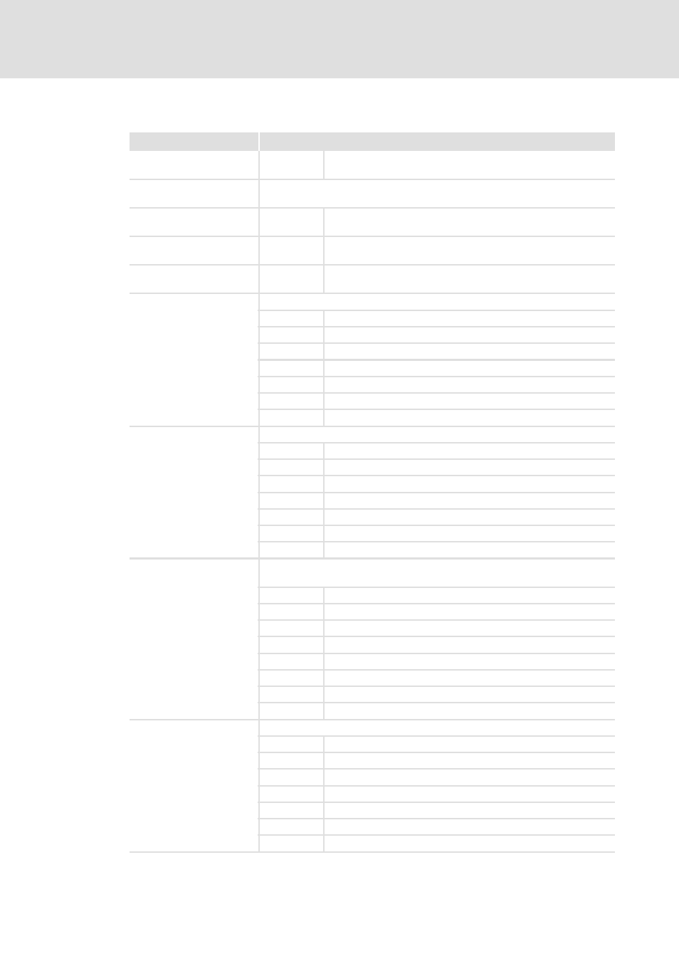
Inputs
Identifier/data type
Information/possible settings
bExecute
BOOL
FALSEÊTRUE Start parameter setting of the analog output module
dwHandle
DWORD
• 9400 ServoPLC: Handle created by FB L_CanInit
• Drive PLC, 9300 Servo PLC, ECS: 10
byNodeAdr
BYTE
1 ... 127 CAN node address of the I/O system
byAnalogModuleNo
BYTE
1 ... 64 Number of the analog output module
bDiagnosticAlarm
BOOL
TRUE Enable diagnostic alarm
byCnt0
InputFrequencyTrackA
BYTE
Counter 1: Input filter of digital input 1, "A1"/"pulse"
2 100 kHz
3 60 kHz
4 30 kHz
6 10 kHz
7 5 kHz
8 2 kHz
9 1 kHz
byCnt0
InputFrequencyTrackB
BYTE
Counter 1: Input filter of digital input 5, "B1"/"direction"
2 100 kHz
3 60 kHz
4 30 kHz
6 10 kHz
7 5 kHz
8 2 kHz
9 1 kHz
byCnt0AlarmFunction
BYTE
Counter 1: Process alarm
A process alarm can be triggered in case of the following events:
bits0 Reserved
bits1 Reserved
Bit 2 Counter limit overflow
bits3 Counter limit underflow
bits4 Comparison value reached
Bit 5 Final value reached
Bit 6 Reserved
Bit 7 Reserved
byCnt0CounterFunction
BYTE
Counter 1: Counting function
0 Continuous counting
1 Single counting, main counting direction is forward
2 Single counting, main counting direction is backward
3 Single counting, no main counting direction
4 Periodic counting, main counting direction is forward
5 Periodic counting, main counting directin is backward
6 Periodic counting, no main counting direction