9 homing methods, Programming – Lenze PM94P01C User Manual
Page 63
PM94P01C
61
Programming
2.15.9 Homing Methods
There are several types of homing methods but each method establishes the:
•
Homing signal (positive limit switch, negative limit switch, home switch ,or index pulse)
•
Direction of actuation and, where appropriate, the direction of the index pulse.
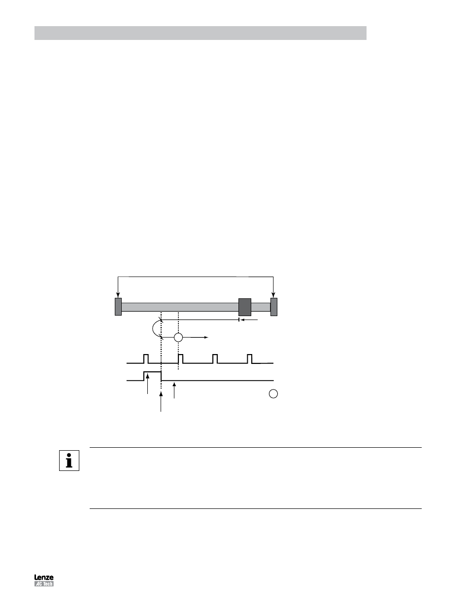
The homing method descriptions and diagrams in this manual are based on those in the CANopen Profile for Drives
and Motion Control (DSP 402). As illustrated in Figure 24, each homing method diagram shows the motor in the starting
position on a mechanical stage. The arrow line indicates direction of motion and the circled number indicates the homing
method (the mode selected by the Homing Method variable).
The location of the circled method number indicates the home position reached with that method. The text designators
(A, B) indicate the logical transition required for the homing function to complete it’s current phase of motion. Dashed
lines overlay these transitions and reference them to the relevant transitions of limit switches, homing sensors, or index
pulses.
Definitions
Positive home switch: goes active at some position, and remains active for all positions greater than that one.
Negative home switch: goes active at some position, and remains active for all positions less than that one.
Intermittent home switch: is one that is only active for a limited range of travel.
Negative Limit Switch
Index Pulse Positions
Switch active (high)
Switch inactive (low)
Starting Position
Direction of Motion
Mechanical Stage Limits
Switch transition
1 Number = Homing Method Number.
Refers to Homing Method Object 0x6098
Position of the number indicates the home position
A
B
1
Figure 24: Homing Terms
NOTE
In the homing method descriptions, negative motion is leftward and positive motion is rightward
BLUE
lines indicate fast velocity moves
GREEN
lines indicate slow velocity moves
RED
lines indicate slow velocity/100 moves