Reference – Lenze PM94P01C User Manual
Page 122
PM94P01C
120
Reference
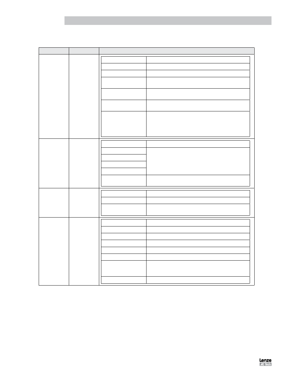
Table 66: Parameter Settings for External Positioning Mode
MVOB Folder
Sub-Folder
Setting
Parameters
--
Parameter Name
Description
Drive Mode
Set to [Position] for Position Mode
Reference
Set to [External] for external Position Mode
Step Input Type
Set to either [Step and Direction ] or [Master Encoder] to match the
Position Controller
System to Master Ratio
Set Electronic Gear Ratio on Reference Signal to the PositionServo
Motor Output
Enable Switch Input
Set to [Run] to allow Enable/Disable of the PositionServo to be
controlled via Input A3 (Dedicated Enable)
Resolver Track
If using Resolver Feedback, set value that represents the pulses per
revolution required on the PositionServo simulated encoder.
0=1024ppr; 1=256ppr; 2=360ppr; 3=400ppr; 4=500ppr; 5=512ppr;
6=720ppr; 7=800ppr; 8=1000ppr; 9=1024ppr; 10=2000ppr;
11=2048ppr; 12=2500ppr; 13=2880ppr; 14=250ppr; 15=4096ppr
IO
Digital IO
Parameter Name
Description
Output 1 Function
Output # indicates Digital Output No. 1-4;
Set value to select Output Functionality;
Output Function Values: 1=Not Assigned; 2=Zero Speed;
3=In Speed Window; 4=Current Limit; 5=Run Time Fault; 6=Ready;
7=Brake; 8=In Position
Output 2 Function
Output 3 Function
Output 4 Function
Hard Limit Switches Action
Set to Enable Inputs A1 and A2 to act as System Hard Limit Switches
and define functionality in the event of an active input.
Limits
Position Limits
Parameter Name
Description
Position Error
Set Position Error Limit at which Position Error Timer starts counting
Max Error Time
Set Maximum Error Time for Position Error Correction before position
error trip occurs.
Compensation
--
Parameter Name
Description
Velocity P-Gain
Set P-Gain for Velocity Loop
Velocity I-Gain
Set I-Gain for Velocity Loop
Position P-Gain
Set P-Gain for Position Loop
Position I-Gain
Set I-Gain for Position Loop
Position D-Gain
Set D-Gain for Position Loop
Position I-Limit
The Position I-Limit will clamp the Position I-Gain compensator to
prevent excessive torque overshoot caused by an over-accumulation
of I-Gain.
Gain Scaling
Apply Scaling Factor to Velocity Gain Set
Note 1: Parameters
highlighted in BLUE
are mandatory/necessary for operation in this mode.