Introduction – Lenze PM94P01C User Manual
Page 20
PM94P01C
18
Introduction
Digital Inputs
-
The PositionServo has twelve digital inputs that are utilized by the drive for decision making in the User Program.
Example uses: travel limit switches, proximity sensors, push buttons and hand shaking with other devices.
-
Each input can be assigned an individual debounce time via MotionView. From the
Parameter Tree, select [IO].
Then select the [
Digital Input] folder. The debounce times will be displayed in the Parameter View Window.
Debounce times can be set between 0 and 1000 ms (1ms = 0.001 sec). Debounce times can also be set via
variables in the user program.
-
The twelve inputs are separated into three groups: A, B and C. Each group has four inputs and share one
common: Acom, Bcom and Ccom respectfully. The inputs are labeled individually as
IN_A1 - IN_A4, IN_B1
- IN_B4 and IN_C1 - IN_C4.
-
In addition to monitoring each input individually, the status of all twelve inputs can be represented as one binary
number. Each input corresponds to 1 bit in the INPUTS system variable. Use the following format:
System
Variable
INPUTS
Bit #
11
10
9
8
7
6
5
4
3
2
1
0
Input
Name
C4
C3
C2
C1
B4
B3
B2
B1
A4
A3
A2
A1
-
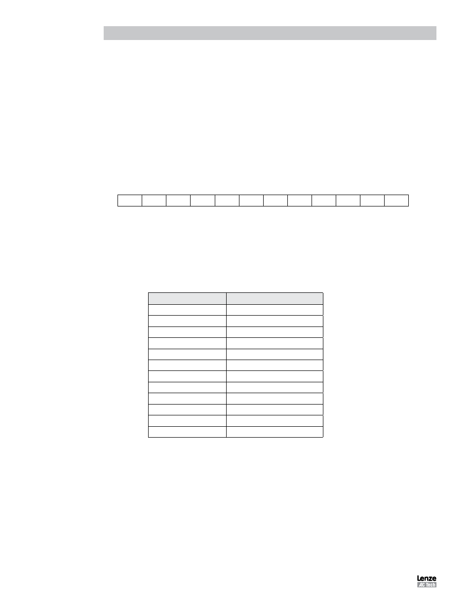
Some inputs can have additional special functionality such as Travel Limit switch, Enable input, and Registration
input. Configuration of these inputs is done from MotionView or through variables in the user program. Input
special functionality is summarized in the table below and in the following sections. The current status of the
drive’s inputs is available to the programmer through dedicated System Flags or as bits of the System Variable
INPUTS. Table 5 summarizes the special functions for the inputs.
Table 5: Input Functions
Input
Special Function
Input A1
negative limit switch
Input A2
positive limit switch
Input A3
Inhibit/Enable input
Input A4
N/A
Input B1
N/A
Input B2
N/A
Input B3
N/A
Input B4
N/A
Input C1
N/A
Input C2
N/A
Input C3
Registration sensor input
Input C4
N/A