2 quick start - external positioning, Reference – Lenze PM94P01C User Manual
Page 121
PM94P01C
119
Reference
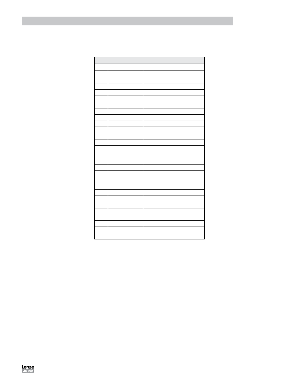
3.3.2 Quick Start - External Positioning
Table 65: Connections for External Positioning Mode
I/O (P3)
Pin
Name
Function
1
MA+
Master Encoder A+ / Step+ input
2
MA-
Master Encoder A- / Step- input
3
MB+
Master Encoder B+ / Direction+ input
4
MB-
Master Encoder B- / Direction- input
5
GND
Drive Logic Common
6
+5V
+5V Output (max 100mA)
7
BA+
Buffered Encoder Output: Channel A+
8
BA-
Buffered Encoder Output: Channel A-
9
BB+
Buffered Encoder Output: Channel B+
10
BB-
Buffered Encoder Output: Channel B-
11
BZ+
Buffered Encoder Output: Channel Z+
12
BZ-
Buffered Encoder Output: Channel Z-
26
IN_A_COM
Digital input group A COM terminal
27
IN_A1
Digital input A1
28
IN_A2
Digital input A2
29
IN_A3
Digital input A3
30
IN_A4
Digital input A4
41
RDY+
Ready output Collector
42
RDY-
Ready output Emitter
43
OUT1-C
Programmable output #1 Collector
44
OUT1-E
Programmable output #1 Emitter
45
OUT2-C
Programmable output #2 Collector
46
OUT2-E
Programmable output #2 Emitter
47
OUT3-C
Programmable output #3 Collector
48
OUT3-E
Programmable output #3 Emitter
49
OUT4-C
Programmable output #4 Collector
50
OUT4-E
Programmable output #4 Emitter
Note 1: Connections
highlighted in BLUE
are mandatory/necessary for operation in this mode.
Note 2: Connections
highlighted in GREEN
are frequently required in applications of this type.