3 application examples, 1 modular decentralised i/o system, Modular decentralised i/o system – Lenze DDS Function library IOSystem User Manual
Page 11: Function library lenzeiosystem.lib, 3application examples, Application examples
Function library LenzeIOSystem.lib
Application examples
3.1
Modular decentralised I/O system
3−1
L
LenzeIOSystem.lib EN 1.7
3
Application examples
The examples were generated with DDS version 2.0. Examples concerning the I/O system are given
in the directory C:\Programme\Lenze\DDS_P_2_20\Projects\IOSystem\Samples
3.1
Modular decentralised I/O system
The modular decentralised I/O system with eight digital inputs and outputs is integrated into a PLC
program with the help of LenzeIOSystem.lib.
During this process, the following steps must be carried out in the given order:
1. Initialise the CAN driver
2. Parameterise the communication conditions
3. Program the process data exchange between PLC and I/O system
4. Initialise the codes
Initialising the CAN driver
Communication between the PLC and the I/O system is based on "unassigned CAN objects"
(control, alarm, diagnostics...). These objects are available in DDS from version 2.x onwards.
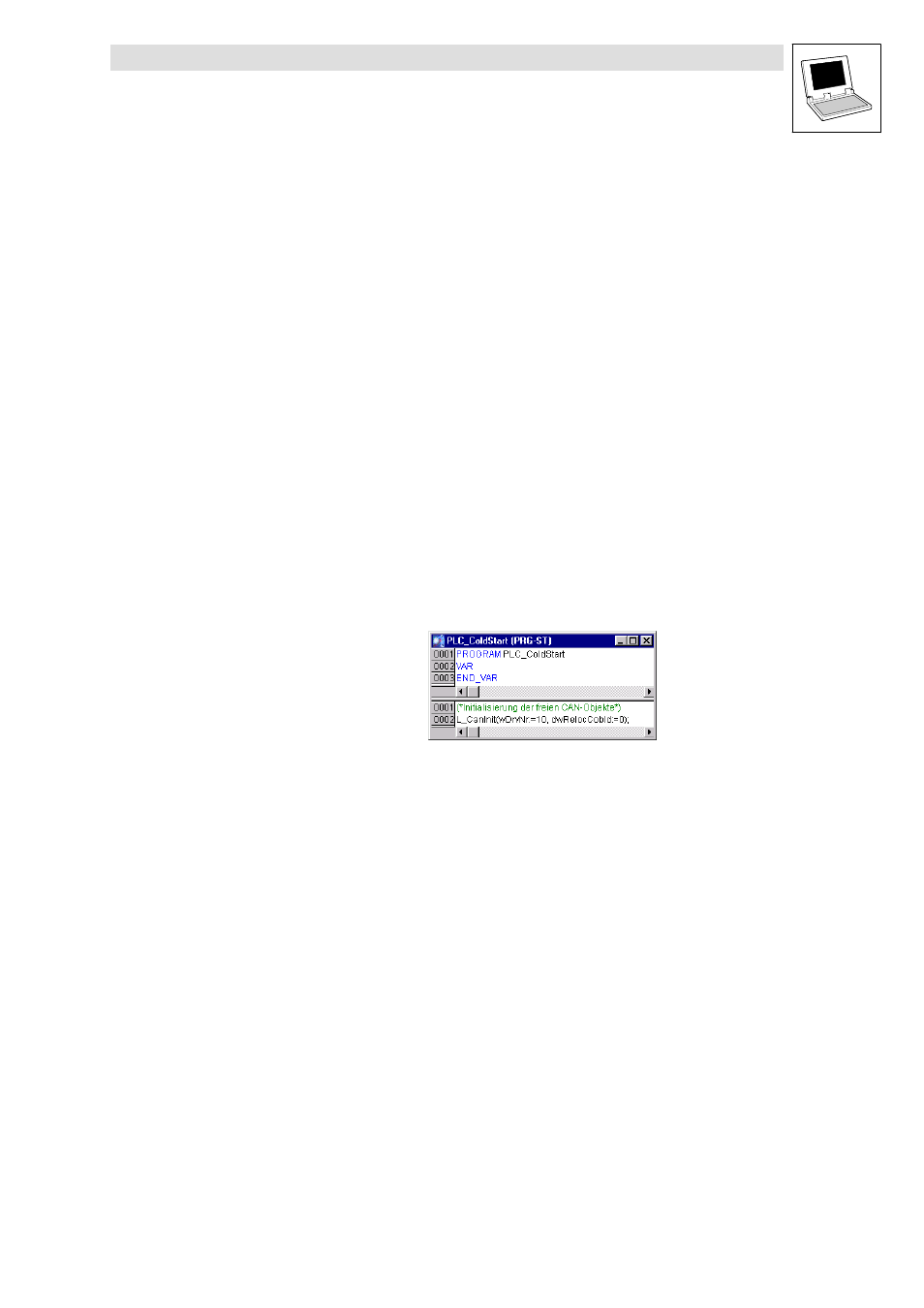
To initialise the unassigned CAN objects, the function L_CANInit must be requested once only in the
system POU PLC_ColdStart.
Parameterising the communication conditions
Function block L_IOParPDO15 for parameterising the communication conditions of PDO1−PDO5 is
integrated into the SFC editor and necessarily is to be used in every project. This function block
specifies the communication parameters in the I/O system.
The values are transferred to the process data block L_IOData15 as a structure (STRUCT) in order
to match the communication parameters of the devices (controller and I/O system).
On program execution, this step is executed only once at the beginning.