9300 servo plc, Ȧȡ ȣ, Ȧȣ ȥ – Lenze Drive PLC Developer Studio 9300 Servo PLC (V8.x) User Manual
Page 82: System blocks, 4 oc6 − i, X t overload monitoring
2.12
MCTRL_MotorControl (node number 131)
9300 Servo PLC
System blocks
2−68
L
9300 Servo PLC EN 5.0
2.12.17.4
OC6 − I
2
x t overload monitoring
The I
2
× t load of the motor is continuously calculated by the controller and displayed in C0066.
I
2
x t monitoring is dimensioned in such a way that it is triggered after 179 s in case of a motor with
a thermal motor time constant of 5 minutes, a motor current of 1.5 x I
r
and a trigger threshold of
100 %.
Two adjustable trigger thresholds serve to define different responses.
·
Adjustable response OC8 (TRIP, warning, off).
– The response is set in C0606.
– The trigger threshold is set in C0127.
– The OC8 response can be used for advance warning.
·
Fixed response OC6−TRIP.
– The trigger threshold is set in C0120.
Behaviour of the I
2
x t monitoring
Condition
I
2
x t monitoring is deactivated.
C0066 = 0 % and
When C0120 = 0 % and C0127 = 0 %, set controller inhibit.
I
2
x t monitoring is stopped.
The current value in C0066 is frozen.
When C0120 = 0 % and C0127 = 0 %, activate controller enable.
I
2
x t monitoring is deactivated.
The motor utilisation is displayed in C0066.
Set C0606 = 3 (off) and C0127 > 0 %.
An error message OC6 or OC8 can only be reset if the I
2
× t load has exceeded the set trigger
threshold by 5 %.
Calculate release time
t + * (C0128) @ ln
ȧ
ȡ
Ȣ
1 *
y ) 1
ǒ
IM
Ir
Ǔ
2
@ 100
ȧ
ȣ
Ȥ
I
M
Actual motor current
I
r
Rated motor current
y
C0120 or C0127
·
The thermal loading capacity of the motor is expressed by the thermal motor time constant
(C0128). The value can be obtained from the rated motor data or contact the manufacturer of
the motor.
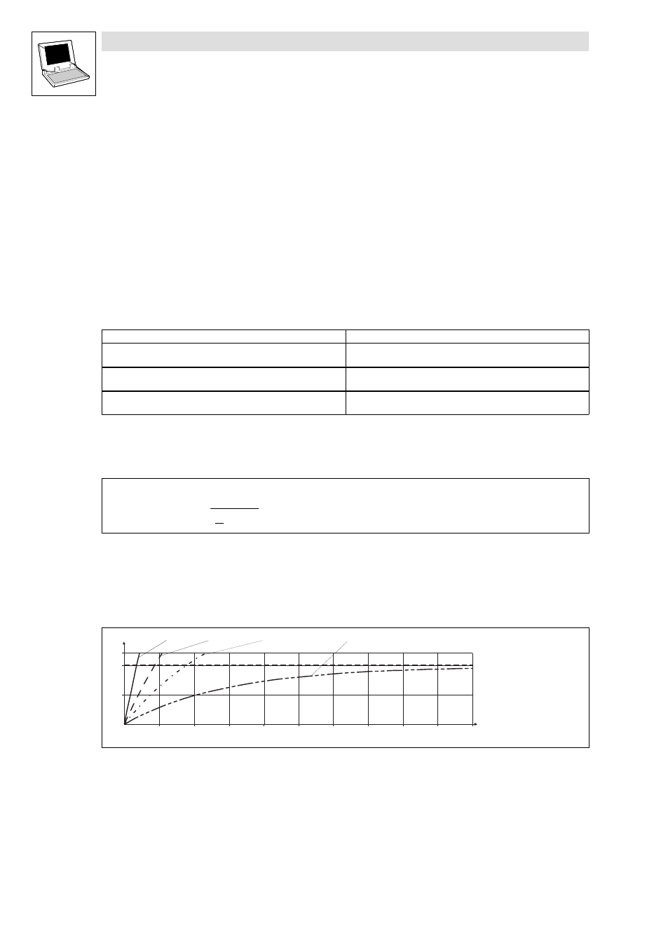
Read release time in the diagram
Diagram for detecting the release times of a motor with a thermal motor time constant of 5 min:
I
= 3 × I
mot
r
0
50
100
120
0
100
200
300
400
500
600
700
800
900
1000
t [s]
I t [%]
2
I
= 2 × I
mot
r
I
= 1.5 × I
mot
r
I
= 1 × I
mot
r
9300std105
Fig. 2−28
I
2
× t monitoring: Release times with different motor currents and trigger thresholds
Imot
Motor current
I
r
Rated motor current
I
2
t
I
2
t load
t
Time