9300 servo plc, System blocks, 3 oc5 − i x t overload monitoring – Lenze Drive PLC Developer Studio 9300 Servo PLC (V8.x) User Manual
Page 81
9300 Servo PLC
System blocks
2.12
MCTRL_MotorControl (node number 131)
2−67
L
9300 Servo PLC EN 5.0
2.12.17.3
OC5 − I x t overload monitoring
Error
Monitoring function
System variable
Possible responses
No.
Display
TRIP
Message
Warning
FAIL−QSP
Off
x015 OC5
I x t overload
MCTRL_bIxtOverload_b
·
· Lenze setting
ü Setting possible
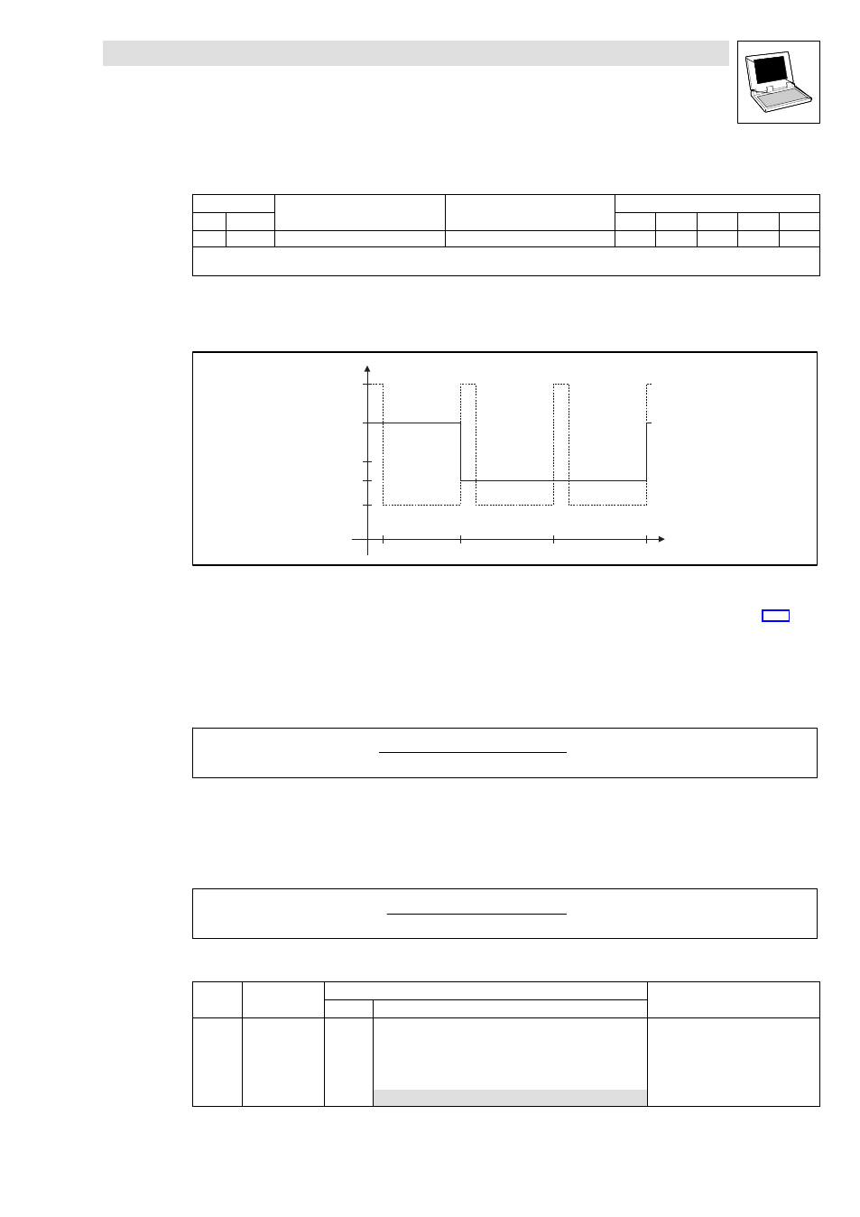
Overcurrent diagram for OC5 fault message
The following diagram shows the maximum permissible overcurrent as a function of time:
150
100
75
200
I
[%]
Motor
10
60
120
180
t [s]
44
Fig. 2−27
Overcurrent diagram
The maximum permissible overcurrent is dependent on the I
max
limit set under C0022.
(
^ 2−60)
I
max
limit sender under C0022
£
150 % I
N
:
·
Within a period of 180 s, the arithmetic mean value of the motor current may not exceed 100
% of the rated device current.
·
Example: Arithmetic mean value to curve
:
60 s
@ 150 % ) 120 s @ 75 %
180 s
+ 100 %
I
max
limit set under C0022 > 150 % I
r
:
·
Within a period of 60 s, the arithmetic mean value of the motor current may not exceed 70 %
of the rated device current.
·
Example: Arithmetic mean value to curve
:
10 s
@ 200 % ) 50 s @ 44 %
60 s
+ 70 %
The current controller load is displayed in C0064:
Code
LCD
Possible settings
IMPORTANT
Lenze
Selection
C0064 Utilization
g
Controller load I x t during the last
180 seconds
·
C0064 >100 % trips OC5.
·
TRIP−RESET is only possible if
C0064 < 95 %.
0
{1 %}
150