9300 servo plc, Appendix – Lenze Drive PLC Developer Studio 9300 Servo PLC (V8.x) User Manual
Page 140
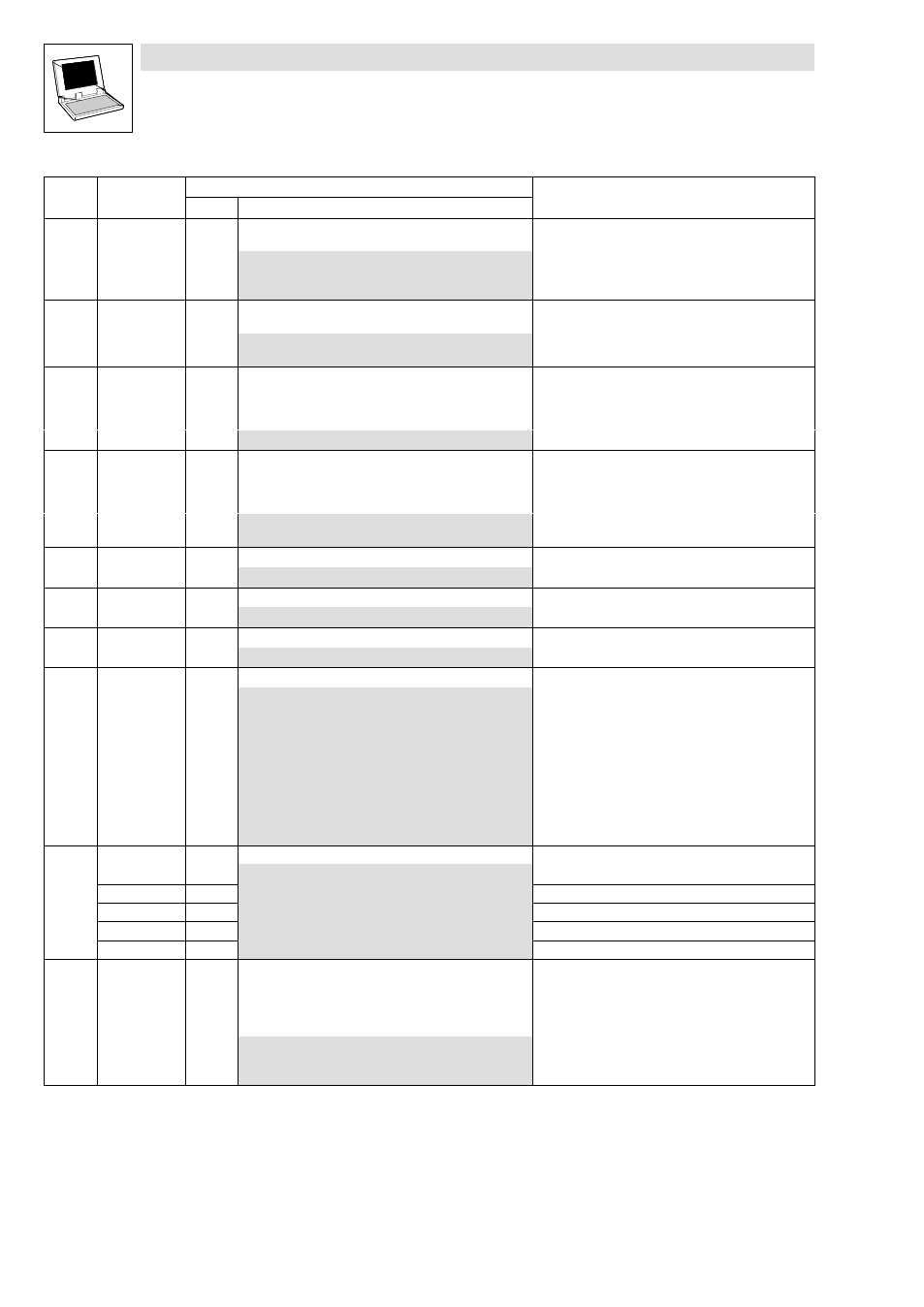
3.6
Code table
9300 Servo PLC
Appendix
3−38
L
9300 Servo PLC EN 5.0
Code
Info
Possible settings
LCD
Code
Info
Selection
Lenze
LCD
C0427 DFIN function
0
Digital frequency input DFIN_IO_DigitalFrequency:
Type of the digital frequency signal
0
2 phases
1
A = Speed / B = Direction
2
A or B = Speed or direction
C0428 DFIN TP sel.
0
Digital frequency input DFIN_IO_DigitalFrequency:
Touch probe selection
0
Touch probe via zero pulse
1
Touch probe through digital input X5/E5
C0429 TP delay
0
Digital frequency input DFIN_IO_DigitalFrequency:
Touch probe delay
·
Compensation of delay times of the TP signal source at
X5/E5
−32767
{1 inc}
32767
C0431 DFIN TP EDGE
0
Digital frequency input DFIN_IO_DigitalFrequency:
Touch probe activation
·
For touch probe via digital input X5/E5
(C0428 = 1)
0
Activation with positive signal
1
Activation with negative signal
C0434 DIS: IN
g
Analog output terminal 62 (AOUT1_nOut_a)
−199.99
{0.01 %}
199.99
C0439 DIS: AOUT2
g
Analog output terminal 63 (AOUT2_nOut_a)
−199.99
{0.01 %}
199.99
C0441 DIS: IN
g
State bus monitoring signal (STATE_BUS_bOut_b)
0
1
C0443 DIS: DIGIT−OUT
g
Digital inputs
0
{hex}
FFFF
Decimal value is bit−coded:
Bit 0
DIGIN_bIn1_b
Bit 1
DIGIN_bIn2_b
Bit 2
DIGIN_bIn3_b
Bit 3
DIGIN_bIn4_b
Bit 4
DIGIN_bIn5_b
Bit 5
STATE−BUS_bIn_b
Bit 6
DIGIN_bCInh_b
Bit 7
Not assigned
X5/E1
X5/E2
X5/E3
X5/E4
X5/E5
C0444 DIS: DIGOUT
g
Digital outputs
0
1
1
DIGOUT_bOut1_b
X5/A1
2
DIGOUT_bOut2_b
X5/A2
3
DIGOUT_bOut3_b
X5/A3
4
DIGOUT_bOut4_b
X5/A4
[C0469] Fct STP key
2
Function of the STOP key of the operating module
·
Selected function is executed when the STOP key is
pressed.
·
Caution: Trouble−free functioning demands that the SB
DCTRL is integrated into the control configuration.
0
Deactivated
1
Controller inhibit (CINH)
2
Quick stop (QSP)