9300 servo plc, System blocks – Lenze Drive PLC Developer Studio 9300 Servo PLC (V8.x) User Manual
Page 52
2.9
DFOUT_IO_DigitalFrequency (node number 22)
9300 Servo PLC
System blocks
2−38
L
9300 Servo PLC EN 5.0
Digital frequency output X10
Technical data
Connection:
Sub−D female connector, 9−pole
Output frequency:
0 − 500 kHz
Ampacity:
Max. 20 mA per channel
Load capacity:
·
With a parallel connection, a maximum of 3 slave drives can be connected.
·
With a series connection, any number of slave drives can be connected.
Properties
·
Two−track with inverse 5 V signals and zero track
·
When PIN 8 (EN) is LOW, the master drive is being initialised (e.g. if the mains was disconnected in the meantime).
The slave drive can thus monitor the master.
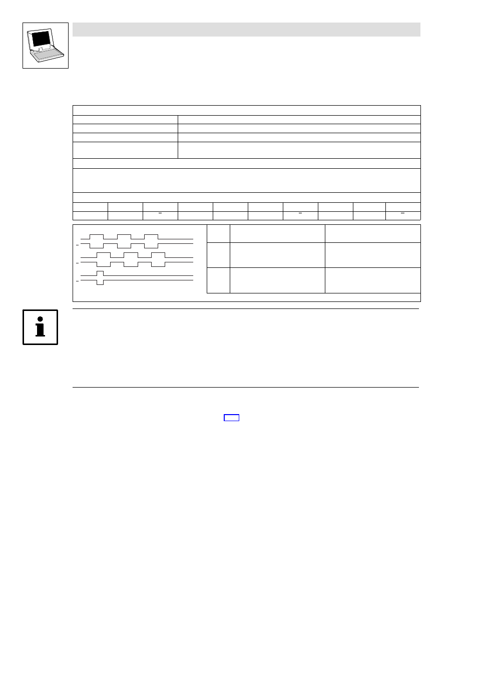
Assignment of the Sub−D connector (X10)
PIN
1
2
3
4
5
6
7
8
9
Signal
B
A
A
+5 V
GND
Z
Z
EN
B
B
B
A
A
Z
Z
Track
CW rotation
CCW rotation
A
leads track B by 90º
(DFIN_nIn_v = positive value)
lags behind track B by 90º
(DFIN_nIn_v = negative value)
B
−
−
Signal sequence with phase shift (CW rotation)
Note!
The digital frequency output X10 has a system−dependent delay time T
d
which can be calculated
using the following formula:
T
d
= Task cycle time (process image cycle) − 1 ms
Example: If DFOUT_nOut_v is written to in a "10−ms task", the signal at X10 has a delay time T
d
of
9 ms (10 ms − 1 ms).
Digital frequency input X9
·
See SB DFIN_IO_DigitalFrequency.
(