9300 servo plc, Appendix – Lenze Drive PLC Developer Studio 9300 Servo PLC (V8.x) User Manual
Page 116
9300 Servo PLC
Appendix
3−14
L
9300 Servo PLC EN 5.0
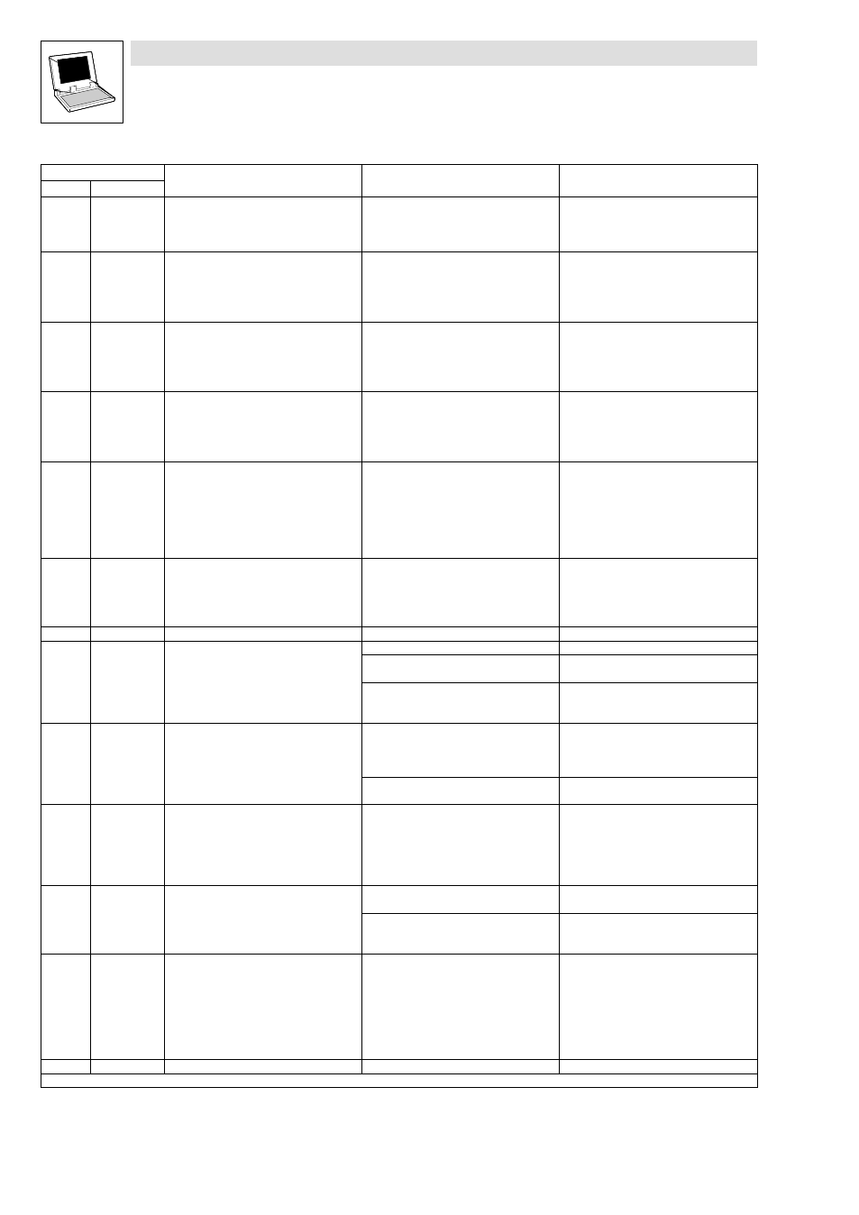
Fault message
Remedy
Cause
Description
No.
Remedy
Cause
Description
Display
x061
CE0
Automation interface (AIF) communication
error
Faulty transfer of control commands via AIF.
·
Plug in the communication
module/keypad XT firmly, screw down, if
necessary.
·
Switch off monitoring (C0126 = 3).
x062
CE1
Communication error on the process data
input object CAN1_IN
CAN1_IN object receives faulty data or
communication is interrupted.
·
Check wiring at X4.
·
Check sender.
·
Increase monitoring time under
C0357/1, if necessary.
·
Switch off monitoring (C0591 = 3).
x063
CE2
Communication error on the process data
input object CAN2_IN
CAN2_IN object receives faulty data or
communication is interrupted.
·
Check wiring at X4.
·
Check sender.
·
Increase monitoring time under
C0357/2, if necessary.
·
Switch off monitoring (C0592 = 3).
x064
CE3
Communication error on the process data
input object CAN3_IN
CAN3_IN object receives faulty data or
communication is interrupted.
·
Check wiring at X4.
·
Check sender.
·
Increase monitoring time under
C0357/3, if necessary.
·
Switch off monitoring (C0593 = 3).
x065
CE4
BUS−OFF state of system bus (CAN)
The controller has received too many faulty
telegrams via the system bus (CAN) and has
disconnected from the bus.
·
Check wiring at X4: Is the bus correctly
terminated?
·
Check shield connection of the cables.
·
Check PE connection.
·
Check bus load, reduce the baud rate if
necessary. (Observe the cable length!)
·
Switch off the monitoring (C0595 = 3).
x066
CE5
Time−out of system bus (CAN)
(communication error of gateway function)
For remote parameterisation (C0370,
C0371) via system bus (CAN):
·
Slave does not respond.
·
Communication monitoring time has
been exceeded.
·
Check wiring of system bus (CAN).
·
Check CAN bus configuration.
0070
U15
Undervoltage of internal 15 V voltage supply
Check voltage supply.
x071
CCR
System fault
Strong interference on the control cables
Control cables must be shielded.
Ground or earth loops in wiring
·
Check wiring.
·
Check PE connection.
After fault correction: completely
deenergise the device (switch off 24 V
supply, discharge DC bus)!
0072
PR1
Checksum error in parameter set 1
CAUTION: The Lenze setting is loaded
automatically!
·
Fault when loading a parameter set.
·
Interruption while transmitting the
parameter set via keypad.
·
Set the required parameters and store
them under C0003 = 1.
·
As to PLC devices, check the use of
pointers.
The stored parameters are incompatible
with the loaded software version.
Store the parameter set under C0003 = 1
first to allow for a faults reset.
0074
PEr
Program error
Error in the program flow
Send the parameter set (on floppy
disk/CD−ROM) with a detailed description of
the problem to Lenze.
After troubleshooting: Deenergise the
device completely (disconnect 24 V
supply, discharge DC bus)!
0075
PR0
Error in parameter set.
The operating system software has been
updated.
Storage of the Lenze setting C0003 = 1.
After troubleshooting: Deenergise the
device completely (disconnect 24 V
supply, discharge DC bus)!
0079
PI
Fault during parameter initialisation
·
An error has been detected during
parameter set transfer between two
controllers.
·
Parameter set does not match the
controller, e.g. when data were
transmitted from a controller with more
performance to a controller with less
performance.
·
Correct parameter set.
·
Check code initialisation values.
After fault correction: completely
deenergise the device (switch off 24 V
supply, discharge DC bus)!
0080
PR6
Too many user codes
Reduce the number of user codes.
x: 0 = TRIP, 1 = Message, 2 = Warning, 3 = FAIL−QSP